

SSGS

SSGS
The document outlines specifications for Ground Spur Pinion Shafts with modules 1.5, 2, 2.5, and 3. The precision grade is JIS grade N7 and JIS grade 3, with a standard full depth gear teeth and a pressure angle of 20°. The material used is S45C, with thermal refinement and induction hardened tooth surfaces, achieving a tooth hardness of 50 to 60 HRC.
The catalog provides detailed measurements for various models (SSGS1.5-10 to SSGS3-13), including shaft diameter, length, pitch diameter, outside diameter, and face width. Profile shift coefficients and center distances for different teeth numbers are also provided.
Allowable torque values, both in N·m and kgf·m, are listed alongside bending strength and surface durability for each model. Backlash values are given as theoretical values for normal direction meshing of identical SSG Spur Gears with 30 teeth.
The document includes tables for calculating center distances when meshing profile shifted spur gears with standard spur gears. It provides formulas and cautions for assembly distances and secondary operations, emphasizing the use of carbide tools due to induction hardened gear teeth.
The document advises on allowable torques, profile shifted gears, backlash values, and secondary operations. It highlights the importance of consulting additional pages for detailed usage conditions and safety concerns during modifications.
Catalog excerpts
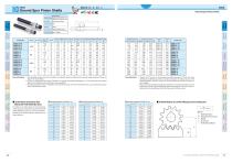
Ground Spur Pinion Shafts Other Bevel Worm Screw Bevel Miter CP Racks R . Internal Helical Spur Products Gearboxes Gear Pair Gears Gears Gears & Pinions ac s Gears Gears Gears Specifications [Caution on Product Characteristics] © The allowable torques shown in the table are calculated values according to the assumed usage conditions. Please see Page 31 for more details. ©10- and 11-tooth gears with a pitch of module 1.5 or greater are profile shifted gears (x = +0.5). Please refer to the below tables for calculating the center distance when assembled. © The backlash values shown in the table are the theoretical values for the normal direction for a pair of identical SSG Spur Gears with 30 teeth in mesh. ■ Center distance of Stock Spur Gears Meshing with Profile Shifted Spur Gears The table on the right shows the center distance of the spur gears (x=0) which can be meshed with profile shifted spur gears (x=+0.5) with module 1. Multiply by the actual module to determine your center distance. ■ Center distance when gear has 12 to 30 teeth (unit : mm) ■ Assembly distance of a profile shifted gear and the meshing rack a = -2 +H+xm Where a : Assembly Distance H : Height of pitch line of rack m : Module z_: No. of Teeth x : Profile Shift Coefficient Other Bevel Worm Screw Bevel Miter CP Racks Racks Internal Helical Spur Products Gearboxes Gear Pair Gears Gears Gears & Pinions Gears Gears Gears 46 For updated information, please see KHK Web Catalog.
Open the catalog to page 1All KHK catalogs and technical brochures
 BB
BB1 Page
 DS
DS2 Pages
 LS
LS1 Page
 SSAY series
1 Page
 Steel Spur Gears
16 Pages
 NSU
NSU5 Pages
 SUKB
SUKB1 Page
 PS / PSA
5 Pages
 SUSL
SUSL2 Pages
 SUS / SUSA
3 Pages
 MSGA / MSGB
6 Pages
 SSG
SSG7 Pages
 SSY
SSY2 Pages
 SSA
SSA3 Pages
 SSR series
1 Page
 SSS series
1 Page
 SSAY/K
2 Pages
 SS series
16 Pages
 PS series
5 Pages
 BSS series
3 Pages
 DSL series
2 Pages
 MSGA ・ MSGB
6 Pages
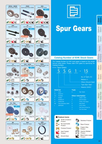 Spur gears
560 Pages

Archived catalogs
 KHK Spur Gear Catalogue
224 Pages
 KHK New Catalogue (2009, April)
48 Pages
 KHK Helical Gear Catalogue
18 Pages
 KHK Internal Gear Catalogue
6 Pages
 KHK Rack Gear Catalogue
28 Pages
 KHK CP Rack Catalogue
18 Pages
 KHK Miter Gear Catalogue
28 Pages
 KHK Bevel Gear Catalogue
42 Pages
 KHK Screw Gear Catalogue
14 Pages
 KHK Worm Gears Catalogue
56 Pages
 KHK Gearbox Catalogue
16 Pages
 KHK Other Products Catalogue
14 Pages
- Flexible coupling
- Sleeve coupling
- Rack and pinion
- Straight-toothed sprocket wheel
- Straight-toothed gear
- Gear coupling
- Metal gear
- Metal shaft
- Hub sprocket wheel
- Precision rack and pinion
- Helical-toothed gear
- Bevel gear
- Straight-toothed rack and pinion
- Steel gear
- Hub gear
- Ground rack and pinion
- Plastic gear
- Sleeve and shear pin coupling
- Shaft gear