

KHK Bevel Gear Catalogue

1 / 42 PagesView full catalog
KHK Bevel Gear Catalogue
Product catalog summary
Overview: The document provides comprehensive technical specifications and guidelines for selecting and using KHK stock bevel gears, including both spiral and straight tooth types. It emphasizes the importance of proper gear selection and assembly to ensure optimal performance.
Specifications: Various types of bevel gears are detailed, such as MBSG, SBSG, MBSA, MBSB, SBS, SB, SBY, SUB, PB, and DB. Each type is described with specific modules, gear ratios, materials, and heat treatments. The document stresses selecting gears based on catalog numbers and provides a formula for determining these numbers.
Procedures: Instructions for selecting mating gears are provided, considering factors like gear strength, material compatibility, and application environment. Precise assembly is crucial to avoid errors such as mounting distance, shaft angle, and offset errors, which can lead to incorrect tooth contact and gear failure.
Standards and Calculations: Gear strength calculations follow JGMA specifications, with assumptions for bending strength and surface durability. Users are advised to compute their own values based on actual usage conditions. Guidelines for calculating radial and thrust loads for hypoid gears are included.
Recommendations: The document recommends using metal mating gears for plastic bevel gears to improve heat conductivity and suggests mounting bevel gears close to bearings to prevent shaft bending. It also advises on using keys, set screws, and taper pins for securing gears to shafts.
Application Hints: Tips for performing secondary operations, such as reboring and machining, are provided. The document warns against excessive pressure during machining to avoid damaging gear teeth and advises on handling changes in plastic gears due to temperature and humidity.
Key Features: High-ratio hypoid gears are highlighted for their cost reduction, high efficiency, high rigidity, and compact assembly. The document compares the efficiency of hypoid gears with worm gears, emphasizing the advantages of hypoid gears in terms of size and motor capacity reduction.
Plastic Bevel Gears: Plastic gears should ideally be paired with steel gears to prevent heat generation and dilation due to lack of lubrication. Specifications include length of bore, face width, holding surface diameter, allowable torque, and backlash. Weight and catalog numbers are provided for various gear models.
Caution on Secondary Operations: Secondary operations may affect gear dimensions due to temperature and moisture sensitivity. Reworking may expose air bubbles in plastic gears.
Injection Molded Bevel Gears: Specifications include precision grade, gear teeth type, pressure angle, material, and tooth hardness. Standard metal bushings can be used to reduce bore size.
Ground Spiral Miter Gears: These gears are high precision and strength, suitable for high-speed, low-noise applications. They are available in various modules and gear ratios, with specifications including precision grade, gear teeth type, pressure angle, helix angle, material, and heat treatment.
Transmission Capability: Tables provide torque and power transmission capabilities for different gear models and speeds. Service factors and impact loads are considered for torque calculations.
General Cautions: Allowable torque values are based on assumed usage conditions. Dimensional tolerances and axial thrust forces should be considered during design and application.
NISSEI Ground Spiral Bevel Gears Overview: This section provides detailed specifications and guidelines for NISSEI Ground Spiral Bevel Gears, including various models and their technical parameters.
Specifications: The gears are precision graded to JIS B 1704 grade 0, with Gleason gear teeth, a pressure angle of 20°, and a helix angle of 35°. The material used is SCM415, with overall carburizing heat treatment, resulting in a tooth hardness of 60 to 63 HRC.
Product Characteristics: Allowable torque is calculated based on output torque at 600 rpm. These gears produce axial thrust forces, with further details available on page 330.
Secondary Operations: No secondary operations can be performed on these precision-finished gears due to the carburizing process. For modifications, refer to the "Caution on Performing Secondary Operations" section on page 358.
Adjusting Tooth Contact: Instructions are provided for centering tooth contact during assembly. Proper assembly ensures contact occurs in the middle of the tooth flank, ideally closer to the toe. Incorrect assembly can lead to noise and uneven wear.
Key Data: Tables include detailed measurements for various gear models, including gear ratio, module, number of teeth, direction of spiral, pitch diameter, face width, and other critical dimensions.
See more
All KHK catalogs and technical brochures
 BB
BB1 Page
 DS
DS2 Pages
 LS
LS1 Page
 SSAY series
1 Page
 Steel Spur Gears
16 Pages
 NSU
NSU5 Pages
 SUKB
SUKB1 Page
 PS / PSA
5 Pages
 SUSL
SUSL2 Pages
 SUS / SUSA
3 Pages
 MSGA / MSGB
6 Pages
 SSGS
SSGS1 Page
 SSG
SSG7 Pages
 SSY
SSY2 Pages
 SSA
SSA3 Pages
 SSR series
1 Page
 SSS series
1 Page
 SSAY/K
2 Pages
 SS series
16 Pages
 PS series
5 Pages
 BSS series
3 Pages
 DSL series
2 Pages
 MSGA ・ MSGB
6 Pages
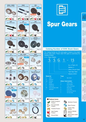 Spur gears
560 Pages

Archived catalogs
 KHK Spur Gear Catalogue
224 Pages
 KHK New Catalogue (2009, April)
48 Pages
 KHK Helical Gear Catalogue
18 Pages
 KHK Internal Gear Catalogue
6 Pages
 KHK Rack Gear Catalogue
28 Pages
 KHK CP Rack Catalogue
18 Pages
 KHK Miter Gear Catalogue
28 Pages
 KHK Screw Gear Catalogue
14 Pages
 KHK Worm Gears Catalogue
56 Pages
 KHK Gearbox Catalogue
16 Pages
 KHK Other Products Catalogue
14 Pages
Related Searches
- Flexible coupling
- Sleeve coupling
- Rack and pinion
- Straight-toothed sprocket wheel
- Straight-toothed gear
- Gear coupling
- Metal gear
- Metal shaft
- Hub sprocket wheel
- Precision rack and pinion
- Helical-toothed gear
- Straight-toothed rack and pinion
- Spur gear
- Hub gear
- Ground rack and pinion
- Sleeve and shear pin coupling
- Shaft gear
*Prices are pre-tax. They exclude delivery charges and customs duties and do not include additional charges for installation or activation options. Prices are indicative only and may vary by country, with changes to the cost of raw materials and exchange rates.
About DirectIndustry
DirectIndustry is a marketplace that offers B2B players a complete experience, from product sourcing to purchase. DirectIndustry is an entity of VirtualExpo Group.
Are you a buyer?
Are you a supplier?