
Catalog excerpts

DISCOVER the Alternatives... ... Agilent MODULAR Products Agilent M9330A Arbitrary Waveform Generator 15-bit, 1.25 GS/s D Brochure TM
Open the catalog to page 1
2 The Agilent Technologies M9330A arbitrary waveform generator (AWG) is capable of creating high-resolution waveforms for radar, satellite, and frequency agile communication systems. Each channel of the M9330A operates at 1.25 GS/s and features 15 bits of vertical resolution giving designers the most realistic, wideband waveforms available from a commercial AWG. • 1.25 GS/s and 15 bits of vertical resolution per channel provides exceptionally realistic wideband waveforms • Dual output channels drive both single-ended and balanced designs without the need for baluns or hybrids • Extended...
Open the catalog to page 2
3 Sequence0 Seq1 Preamble Waveform repeat Loop repeat Seq2 Waveform repeat Seq3 Waveform repeat Loop repeat Sequence repeat Seq4 Waveform repeat Seq5 Waveform repeat Seq6 Waveform repeat Loop repeat Figure 2. Create sophisticated signal scenarios by looping and nesting waveforms. Create long scenario simulations Multiply the effective size of on-board memory through the use of the M9330A’s advanced sequencing engine. Uniquely define how waveform segments are played through looping and nesting of stored waveforms. This capability also gives users the ability to create new signals from...
Open the catalog to page 3
4 System scalability Create phase-coherent, multi-emitter simulations using the M9330A’s precision SYNC clock. A single M9330A can drive a total of eight AWG modules to synchronize their outputs on a sample-by-sample basis. Any number of modules can be synchronized with simple driver hardware. The AWG also includes multiple front-panel triggers and markers for complete system synchronization. Ease-of-use The M9330A’s graphical user interface guides developers through module setup and waveform file transfers. Users can quickly configure the instrument’s signal conditioning paths, marker and...
Open the catalog to page 4
5 Dynamic Sequencing (Option 300) The dynamic sequencing software enables radar and military communications engineers to build custom signal scenarios on the fly. Engineers can dynamically access up to 16 k of previously stored sequences through a 16-bit interface and replay these complex waveforms to respond to changing threat environments, or to create signals where the next waveform to be played is not known in advance. Dynamic Synthesis (Option 330) The direct digital synthesis (DDS) software enables radar and emerging communications engineers to create basic waveforms in the AWG’s...
Open the catalog to page 5
6 KEY CHARACTERISTICS Figure 9. Excellent harmonic and spurious performance are available across the full bandwidth of each channel. Figure 10. Spurious performance outstanding at low signal frequencies. Channels Two independent channels available as baseband or IF outputs CH1: Single-ended and differential CH2: Single-ended and differential Modulation bandwidth 500 MHz per channel (1 GHz IQ bandwidth) Resolution 15 bits (1/32,768 levels) Output spectral purity – (CH1 and CH2) • Harmonic distortion: –65 dBc for each channel DC to 500 MHz • Non-harmonic spurious: –75 dBc for each channel 1...
Open the catalog to page 6
7 KEY CHARACTERISTICS CONTINUED Sample clock Internal Fixed 1.25 GS/s Internal clock output +3 dBm nominal External clock input Tunable 100 MS/s to 1.25 GS/s External clock input drive level +5 to –15 dBm typical Phase noise characteristics 1 kHz: –95 dBc/Hz 10 kHz: –115 dBc/Hz 100 kHz: –138 dBc/Hz 1 MHz: –150 dBc/Hz Noise floor –150 dBc/Hz Accuracy Same as 10 MHz timebase input Frequency reference Input drive level +2 to +12 dBm into 50 Ù (+2 dBm nominal) Waveform length 8 MS per channel (16 MS with option 016) Minimum waveform length 128 samples Waveform granularity 8 samples Segment 1 to...
Open the catalog to page 7
8 KEY CHARACTERISTICS CONTINUED 1. A sync clock cycle is clock/8. Scenario jump modes Scenario jumps determine how a sequence responds to a jump trigger. There are no discontinuities in a scenario jump other than those imposed by the waveform data. Three modes are available to control scenario jumps: Jump immediate • Jumps immediately to the next specifie scenario address with a fixed latency. End of waveform • The current waveform (including repeats) is completed before jumping to a new scenario. End of scenario • The current scenario is completed before jumping to a new scenario. Jump...
Open the catalog to page 8
9 KEY CHARACTERISTICS CONTINUED External markers Markers can be defined for each waveform segment. Number of outputs 4 each SMB female Marker polarity Negative, positive Output impedance 50 Ù Marker low level 100 mV nominal into high impedance load Marker high level 3.2 volts nominal into high impedance load Marker timing resolution Clock/8 (6.4 ns at full rate) Marker latency Marker precedes analog output and is adjustable in 2 sample clock period steps. Marker latency repeatability < 100 ps Marker width Programmable with from 1 to 256 sync clock cycles 1 Marker delay Programmable from –8...
Open the catalog to page 9
10 GENERAL CHARACTERISTICS Power Supply +3.3 VDC, 11.2 W +5 VDC, 22 W +12 VDC, 5 W –12 VDC, 5 W Total power 43.2 W Environmental Samples of this product have been type tested in accordance with the Agilent Environmental Test Manual and verified to be robust against the environmental stresses of Storage, Transportation, and End-use; those stresses include but are not limited to temperature, humidity, shock vibration, altitude, and power line conditions. Test methods are aligned with IEC 60068-2 and levels are similar to MIL-PRF-28800F Class 3. Operating temperature 0 °C to +55 °C Storage...
Open the catalog to page 10
11 ORDERING INFORMATION Figure 11. Agilent M9330A AWG with controller in PXI chassis. Model Description M9330A Arbitrary waveform generator with 8 MS memory per channel Option Description M9330A-M16 Waveform memory expansion to 16 MS memory per channel M9330A-300 Enabling software for 16-bit dynamic sequencing M9330A-330 Direct digital synthesis software M9330A-350 Function generator software NOTE: For the M9330A to work properly, at least one PXI chassis and one PXI controller type must be available. Web resources Visit our web sites for additional product information and literature....
Open the catalog to page 11All KEYSIGHT TECHNOLOGIES catalogs and technical brochures
-
 Network Visibility Products
24 Pages
-
 RF Products
20 Pages
-
 Basic Instruments
34 Pages
-
 InfiniiVision 2000 X-Series
31 Pages
-
 Signal Analyzers X-Series
21 Pages
-
 KeysightCare
8 Pages
-
 FieldFox and Nemo Handy
4 Pages
-
 Impedance and Network Analysis
42 Pages
-
 E4990A Impedance Analyzer
12 Pages
-
 Keysight N6780 Series
10 Pages
-
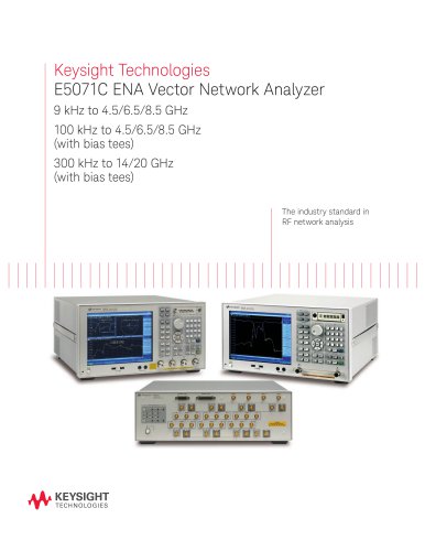 E5071C ENA Network Analyzers
18 Pages
-
 Keysight Process Analysis
7 Pages
-
 BenchVue Software
2 Pages
-
 Keysight Process Analysis
7 Pages
-
 PXI RF Switch Modules
2 Pages
-
 I/O Hardware
18 Pages
-
 Digital Multimeters
28 Pages
-
 Data Acquisition - DAQ
32 Pages
-
 PCIe Digitizers
8 Pages
-
 2015 Optical Component Test
40 Pages
-
 Power Products Catalog
215 Pages
-
 N9000A CXA Signal Analyzer
2 Pages
-
 Agilent 89600 VSA Software
8 Pages
-
 X-Series
23 Pages
-
 CXA X-Series
8 Pages
-
 SOLUTION BROCHURE
6 Pages
-
 Waveguide Power Sensors
2 Pages
-
 Power Meters and Power Sensors
34 Pages
-
 E7515A UXM Wireless Test Set
2 Pages
-
 E5063A Network Analyzer
8 Pages
-
 N9320B RF Spectrum Analyzer
12 Pages
-
 E5052B Signal Source Analyzer
21 Pages
-
 N9038A MXE EMI Receiver
22 Pages
-
 RDX Test Solutions for DigRF
17 Pages
-
 M9252A DigRF Host Adapter
2 Pages
-
 M9502A and M9505A
12 Pages
-
 Oscilloscopes
16 Pages
-
 Agilent Power Products
31 Pages
-
 LIGHTWAVE CATALOG VOLUME I 2013
40 Pages
-
 U4301A PCIe Analyzer
7 Pages
-
 N9030A PXA Signal Analyzer
32 Pages


Archived catalogs
-
 Agilent Technologies - Catalog
40 Pages