
Catalog excerpts

E5052B Signal Source Analyzer Data Sheet
Open the catalog to page 1
Description Specification RF IN connector Type-N (female), 50 ohm nominal Input attenuator 0 to 35 dB (in 5 dB step) Input damage level AC >+23 dBm, DC > 5V Describes performance that will be met by a minimum of 80% of all products. It is not guaranteed by the product warranty. Supplemental performance data (SPD): Represents the value of a parameter that is most likely to occur; the expected mean or average. It is not guaranteed by the product General characteristics or nominal (nom.): A general, descriptive term that does not imply a level of performance. It is not guaranteed by the...
Open the catalog to page 2
Phase Noise Measurement Table 1-2. Phase noise measurement performance Description Measurement frequency bands RF frequency tracking range Measurement parameters SSB phase noise [dBc/Hz], Spurious noise [dBc], Integrated rms phase deviation [deg, rad] or time jitter [s], Residual FM [Hz rms] 1 data trace and 1 memory trace with ‘data math’ functions Measurement trigger source: internal/external/manual/bus Offset frequency range (effective) RF carrier signal > 1 GHz (> 400 MHz for wide capture mode) 1 Hz to 100 MHz 1 Hz to 40 MHz (wide capture mode) 10 Hz to 100 MHz 10 Hz to 40 MHz (wide...
Open the catalog to page 3
Phase Noise Measurement – cont’d Table 1-3. SSB phase noise sensitivity (dBc/Hz) in normal capture range mode (E5052B) LO optimization: < 150 kHz, Ref. BW: narrow, correlation = 1, RF input: +5 dBm, start offset frequency: 1 Hz, measurement time = 12.9 sec RF input frequency Offset frequency [Hz] from the carrier 1 Table 1-3-W. SSB phase noise sensitivity (dBc/Hz) in wide capture range mode (E5052B) (SPD) LO optimization: < 150 kHz, Ref. BW: narrow, correlation = 1, RF input: +5 dBm, start offset frequency: 1 Hz, measurement time = 12.9 sec RF input frequency Offset frequency (Hz) from the...
Open the catalog to page 4
Phase Noise Measurement – cont’d E5052B SSB-PN Sensitivity SSB phase noise [dBc/Hz] SSB phase noise [dBc/Hz] Figure 1-2. SSB phase noise sensitivity (E5052B Option 011, SPD) (LO < 150 kHz optimized, +5 dBm input, start offset frequency = 10 Hz, measurement time = 3.3 sec.) E5052B SSB-PN Sensitivity Change by L.O. Phase Optimization @1 GHz E5052B SSB-PN Sensitivity Improvement by Correlation @1 GHz SSB phase noise [dBc/Hz] SSB phase noise [dBc/Hz] Figure 1-1. SSB phase noise sensitivity (E5052B, SPD) (LO < 150 kHz optimized, +5 dBm input, start offset frequency = 1 Hz, measurement time =...
Open the catalog to page 5
Frequency and RF Power, DC Supply Current Measurements Table 3-1. Frequency and power measurement performance Description Measurement frequency bands Sweep parameters DC control voltage (Vc) DC supply voltage (Vs) Measurement parameters Full analysis capability available for Frequency [Hz, ΔHz, %, ppm], Tuning sensitivity (Δf/ΔVc)[Hz/V], frequency pushing (Δf/ΔVs)[Hz/V], RF power level [dBm], DC supply current [A], ‘Meter mode’ is also available. No ‘Analysis mode’. Only ‘Meter mode’ is available. Frequency [Hz], RF power [dBm], DC supply current [A] Frequency resolution Frequency...
Open the catalog to page 6
Transient Measurement Table 4-1. Transient measurement performance Description Target frequency range Measurement parameters Narrowband mode Wideband mode Frequency, RF power, phase Frequency Frequency transient bandwidth Wideband Narrowband Frequency measurement Resolution Uncertainty Residual FM1 RF power measurement Power level range Resolution Uncertainty See Table 4-2. 3.125 kHz/ 25 kHz/ 200 kHz/ 1.6 MHz 25.6 MHz (> carrier 200 MHz) 80 MHz (> carrier 800 MHz) See Table 4-2. through Table 4-8. ± (resolution + time-base uncertainty) 1 Phase measurement (when DUT signal is locked to a...
Open the catalog to page 7
Transient Measurement/Wideband Mode Table 4-2. Wideband mode frequency resolution vs. time span and frequency band Wideband mode Transient time span (X-axis) setting Measurement point
Open the catalog to page 8
Transient Measurement/Narrowband Mode Table 4-3. Narrowband mode (80 MHz span)/frequency resolution vs. time span Time span [s] Measurement point Table 4-4. Narrowband mode (25.6 MHz span)/frequency resolution vs. time span Time span [s] Measurement point Table 4-5. Narrowband mode (1.6 MHz span)/frequency resolution vs. time span Time span [s] Measurement point Table 4-6. Narrowband mode (200 kHz span)/frequency resolution vs. time span Time span [s] Measurement point Table 4-7. Narrowband mode (25 kHz span)/frequency resolution vs. time span Time span [s] Measurement point Table 4-8....
Open the catalog to page 9
AM Noise Measurement Table 5-1. AM noise measurement performance Description Effective offset frequency range 10 Hz to 40 MHz (@ > carrier 400 MHz) 10 Hz to 10% of carrier frequency (@ < carrier 400 MHz) ± 4 dB (100 Hz to 1 kHz offset) typical ± 2 dB (1 kHz to 1 MHz offset) typical ± 3 dB (1 MHz to 40 MHz offset) typical Spurious level < –65 dBc/Hz (at > 1 kHz offset) typical Measurement trigger continuous/single/hold source: internal/external/manual/bus Table 5-2. AM noise sensitivity [dBc/Hz] correlation = 1, RF input: 0 dBm, > 400 MHz AM noise sensitivity Offset frequency (Hz) from the...
Open the catalog to page 10
Baseband Noise Measurement Table 6-1. Baseband noise measurement performance Description Baseband input connector Measurement frequency range Measurement parameters dBV/Hz, dBm/Hz, V/√Hz Measurement level range Baseband input damage level Noise floor level Measurement trigger continuous/single/hold source: internal/external/manual/bus Table 6-2. Baseband noise floor [dBm/Hz] correlation = 1, baseband input: 0 ohm terminated BB noise floor E5052B start frequency = 1 Hz, measurement time = 13 s specification E5052B Option 011 start frequency = 10 Hz, measurement speed = 3.3 s specification...
Open the catalog to page 11
General Information Table 8-1. Front panel information Description Supplemental information (nominal) SMA (female), 50 ohm See the simplified block diagram. Probe DC power output Ground terminal 10.4 inch TFT color LCD with touch screen 1,024 x 768 resolution1 Table 8-2. Rear panel information Description External trigger input port Connector Input signal level Supplemental information (nominal) Trigger pulse width BNC (female) TTL level, (0 V to +5 V) Threshold Low: 0.5 V, High: 2.1V > 2 μs Trigger polarity positive/negative edge selectable Auxiliary output port Connector Output signal...
Open the catalog to page 12All KEYSIGHT TECHNOLOGIES catalogs and technical brochures
-
 Network Visibility Products
24 Pages
-
 RF Products
20 Pages
-
 Basic Instruments
34 Pages
-
 InfiniiVision 2000 X-Series
31 Pages
-
 Signal Analyzers X-Series
21 Pages
-
 KeysightCare
8 Pages
-
 FieldFox and Nemo Handy
4 Pages
-
 Impedance and Network Analysis
42 Pages
-
 E4990A Impedance Analyzer
12 Pages
-
 Keysight N6780 Series
10 Pages
-
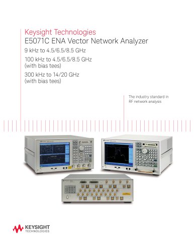 E5071C ENA Network Analyzers
18 Pages
-
 Keysight Process Analysis
7 Pages
-
 BenchVue Software
2 Pages
-
 Keysight Process Analysis
7 Pages
-
 PXI RF Switch Modules
2 Pages
-
 I/O Hardware
18 Pages
-
 Digital Multimeters
28 Pages
-
 Data Acquisition - DAQ
32 Pages
-
 PCIe Digitizers
8 Pages
-
 2015 Optical Component Test
40 Pages
-
 Power Products Catalog
215 Pages
-
 N9000A CXA Signal Analyzer
2 Pages
-
 Agilent 89600 VSA Software
8 Pages
-
 X-Series
23 Pages
-
 CXA X-Series
8 Pages
-
 SOLUTION BROCHURE
6 Pages
-
 Waveguide Power Sensors
2 Pages
-
 Power Meters and Power Sensors
34 Pages
-
 E7515A UXM Wireless Test Set
2 Pages
-
 E5063A Network Analyzer
8 Pages
-
 N9320B RF Spectrum Analyzer
12 Pages
-
 N9038A MXE EMI Receiver
22 Pages
-
 RDX Test Solutions for DigRF
17 Pages
-
 M9252A DigRF Host Adapter
2 Pages
-
 M9502A and M9505A
12 Pages
-
 Oscilloscopes
16 Pages
-
 Agilent Power Products
31 Pages
-
 LIGHTWAVE CATALOG VOLUME I 2013
40 Pages
-
 U4301A PCIe Analyzer
7 Pages
-
 N9030A PXA Signal Analyzer
32 Pages


Archived catalogs
-
 Agilent Technologies - Catalog
40 Pages