- Products
- Catalogs
- News & Trends
- Exhibitions
Crank lifting system Ket-Twist 660 3053
1 /2Pages

Crank lifting system Ket-Twist 660 3053
1 /2Pages
Catalog excerpts

Crank lifting system Ket-Twist 660 3053 Double telescopic Description Ket-Twist is a fast, double-telescoping, crank-operated lifting system for individually adjusting the working height of tables. The system allows a maximum stroke of 660 mm, requiring a minimal installation lenght of just 575 mm. Each turn of the crank lifts the table top about 40 mm. Ket-Twist 660 is designed for 2-leg table frames, which have a minimum of friction loss. It works smoothly and easily even with table loads of up to 40 kg. Lifting Systems Table / Screen Connecting tube 3052.40-V01LXXXX Deflection gear with brake unit 3052.00-V02AXXX Special features Crank handle 5187.00-0032 ▪▪ Compact design: Maximum stroke with minimal installation length ▪▪ Fast adjustment: Maximum height change with just 16.5 turns ▪▪ Connection tube in customized length ▪▪ Design fast and easy assembly ▪▪ Quick, easy assembly ▪▪ Independent of electrical connections: Flexibility in the room arrangement XXXX Length of connecting tube: XXXX in mm Technical data Technical notes Stroke: 660 mm* Retracted length E: 575 mm* Recommended table load: 0 – 40 kg Static self-locking: ≤ 120 kg Adjustment path per revolution: 40 mm Spindle pitch: 2 x 20 mm Ratio: 1:1 Gas spring force: 2 x 250 N/ Hubeinheit Crank lifting system Lifting unit (right and left identical) Gas spring assembly (each right and left) Connecting tube (Customized) Defelction gear with brake unit (Customized) Installation length* ▪▪ Optimum user comfort of the overall system can be only achieved by precise matching of the weight of the plate support, the table top and the guide columns as well as the friction loss of the guide. This coordination is necessary, because the characteristics of different table systems are always individual and must be taken into consideration in the system design. ▪▪ Ket-Twist components must be ordered separately. ▪▪ Upon request the lifting system can also be cus- tom dimensioned, i.e. other lift and installation lengths are possible. ▪▪ Table manufacturer is responsible for integration of the gas spring assembly. ▪▪ Safety instruction: Gas springs can develope high acceleration forces. Please handle the assembly and this disassembly with care and diligence. * Other dimensiones can be manufactured on reques
Open the catalog to page 1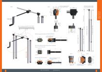
ø 4(2x) Throughgoing holes for mounting screw M4 Lifting Systems Table / Screen Lifting unit 3053.00-0001 Gas spring 3053.16-0001 Deflection gear with brake unit 3052.00-V02AXXX b Alternative: Deflection gear with brake unit separatly Brake unit 3052.09-V01AXXX A ø 4(2x) Throughgoing holes for mounting screw M4
Open the catalog to page 2All Ketterer catalogs and technical brochures
 Worm Gears
36 Pages
 Bevel Gears
28 Pages
 Lifting-Systems and Accessories
44 Pages
 Lifting Units and Accessories
54 Pages
 BLDC Technology
34 Pages
 Wheel hub motors
22 Pages
 Torque-Motors t-Rex
20 Pages
 Worm gearbox family Ket-Motion
30 Pages
 Ketterer Building Drives
11 Pages
 Ketterer Home & Care Solutions
11 Pages


- Liebherr electric motor
- Liebherr DC motor
- Liebherr actuator
- Liebherr multipole motor
- Electric gearmotor
- Liebherr linear actuator
- Liebherr electric actuator
- Liebherr coaxial gear reducer
- Liebherr brushless motor
- Precision gearhead
- Profile
- Liebherr 24 V motor
- Direct current gear-motor
- Liebherr right angle gear reducer
- Compact gearhead
- Solid-shaft gearhead
- Metal profile
- Liebherr compact motor
- Liebherr 12 V motor
- Hollow-shaft gearhead