- Catalogs
- Kennametal
- Tool Selection
Tool Selection
1 /3Pages

Tool Selection
1 /3Pages
Catalog excerpts
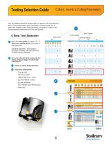
Tooling Selection Guide Cutters, Inserts & Cutting Parameters This new Milling Selection Guide leads you easily to the tool selection and to the corresponding user information. 6 steps enable you to select the suitable cutter, insert geometry and grade in relation with recommended parameters for Feed and Speeds. 1 Body Fixation Family Range Diameter Range Ramping angles High Feed Shell Mills Facing pitch Technical Information Diameter Range Select a Cutter Body Diameter Go to the referred Family page with the entire product range and technical information Body Fixation Available diameters, body fixation and type of inserts can also be found. (7792VX family selected) Dimensions (inch) Insert Shape and Size Slotting Shoulder Contour Milling Family Range Go to the Tool guide on page 10 - 17. Select the milling family according to the application. Modular Heads 6 Step Tool Selection Helical hole (min - max) ap max Helical / Linear ae max plunging High Feed Milling Cutter Helical Interpolation Helical Interpolation with Bore Hole Item Description Slotting / Shoulder Dimensions (inch) Spiral / Circular Weldon Shank 7792VXD09 Shell Mill Fixation - Coarse, Medium and Fine Pitch 029476 029477 030431 030432 030433 Item Description Dimensions (inch) Spares Screw Tightening in. lbs. Note: For cylindrical shank extensions in high density alloy with through coolant refer to page 86. Shell Mill Fixation 7792VXD09 Technical Information (inch) Product Dimensions Ramping Angle A° B° Item Description Modular Head Facing Pitch Helical Interpolation Facing Pitch Ramp angle A uses one outside cutting edge only. Ramp angle B uses two cutting edges (one outside and one inside edge). A A = max ramp angle utilizing full face contact B = max ramp angle utilizing full contact + internal corner radius
Open the catalog to page 1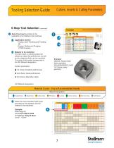
Select the Insert according to the application and material to be machined. ^i> Application Section • Facing, Semi-Finishing and Finishing Or • Facing, Slotting and Plunging (7792VX series) ^2| Material to be machined For each insert, a colored symbol will advise you about the performance, as well as the materials which can be machined. The color of the symbol corresponds to the ISO Material designation. Symbol explanation: ^ 1st choice: Excellent performance ■ 2nd choice: Good performance • 3rd choice: Alternative option Milling Inserts & Recommended Feeds Example: Material: Alloyed Steel facing...
Open the catalog to page 2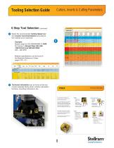
Tooling Selection Guide Cutters, Inserts & Cutting Parameters 6 Step Tool Selection (continued) Speed vc (SFM) Wear Resistance Coolant Recommendation Select the recommended Cutting Speed (vc) and Coolant recommendations according to the material to be machined. France: AFNOR Austenitic + Ferritic 300 series Spheroidal-Ductile GGG-FGS Stainless Steel Grey GG-Ft Cast Iron Aluminum & Alloys Cobalt Based Nickel Based Titanium Based High Temperature Alloys Hard Materials Aluminum + Silicon > 16% Si 92 HBN Iron Based Uncoated Micrograin Alloyed Steel Material specifications can be found in the Materials...
Open the catalog to page 3All Kennametal catalogs and technical brochures
 CB11 Stack-On
2 Pages
 Grinder Tips
16 Pages
 Grader Blades
40 Pages
 Road Rehabilitation • Road King
24 Pages
 Underground Mining
182 Pages
 ROCTEC ecoline
1 Page
 Conforma Clad X2™
2 Pages
 INNOVATIONS 2020
84 Pages
 INNOVATIONS 2019
156 Pages
 Tooling Systems News 2018
60 Pages
 Oilfield Radial Bearings
2 Pages
 Cladding Formulas Oilfield
2 Pages
 General Conveyance Equipment
4 Pages
 Twin-Screw
2 Pages
 EDM Blocks Brochure
8 Pages
 KMT_Wear Solutions_Brochure
12 Pages
 Alloys Brochure Direct
28 Pages
 Kennametal Stellite Alloys
15 Pages
 Composite Rods
1 Page
 Mill Roll Brochure
8 Pages
 Snowplow Blades
1 Page
 KenCast Wear Protection
20 Pages
 7690VA09
3 Pages
 Indexable Milling Index
8 Pages
 Milling geometries quick
9 Pages
 Milling grades
4 Pages
 Specialty Carbide Catalog
16 Pages
 Tooling Systems 2013 Catalog Sections
1576 Pages
 INNOVATIONS CATALOGUE 2015
260 Pages
 Kennametal Innovations 2014
630 Pages
 KMT KBH20 metric
18 Pages
 Master Catalog 2013 Complete - metric
2122 Pages
 Railroad Brochure
24 Pages
 Abrasive Blast Nozzles Catalog
60 Pages
 Surface Mining Catalog
42 Pages
 Holemaking Taps (metric)
118 Pages
 Threading
108 Pages
 O.D. / I.D. Toolholders
162 Pages
 PCD / PCBN Inserts
66 Pages
 ISO / ANSI Inserts
132 Pages
 Thread Mills
20 Pages
 Copy Mills
118 Pages
 Slotting Cutters
56 Pages
 Shoulder Mills
96 Pages
 Face Mills
138 Pages
 Solid End Milling
118 Pages
 Taps
Taps194 Pages
 Hole Finishing
214 Pages
 Indexable Drills
108 Pages
 Combination Tools
28 Pages
 Modular Drills
62 Pages
 Solid Carbide Drills
112 Pages


- Chuck
- Lumibird solid milling cutter
- Lumibird drill bit
- Milling tool with replaceable insert
- Steel milling cutter
- Lumibird metal milling cutter
- Lumibird solid drill bit
- Lumibird clamping milling cutter
- Grade
- Lumibird milling cutter with cylindrical shank
- Lumibird end mill
- Lumibird face milling cutter
- Lumibird shell-end milling cutter
- Cast iron milling cutter
- Lumibird indexable insert milling cutter
- Solid carbide milling cutter
- Ball nose milling cutter
- Lumibird cutting milling cutter
- Lumibird corner radius milling cutter