- Catalogs
- Keko Varicon
- capacitors 2008/2009
capacitors 2008/2009
1 /36Pages

capacitors 2008/2009
1 /36Pages
Catalog excerpts

Terminology and General Information - DISC CAPACITORS Term AC Capacitor RFI Suppression Capacitor Capacitor of Class X Capacitor of Class Y Rated AC Voltage DC operating voltage which may be applied continuously to the terminations of a capacitor at any temperature between the lower and the upper category temperature An impulse voltage is an aperiodic transient voltage of a defined waveform as decribed in IEC 60-1 Impulse Voltage C and tan d Measuring and Testing Conditions Definition A capacitor designed essentially for application with a power - frequency alternating voltage A capacitor used...
Open the catalog to page 2
Contents : Page Terminology & General Information - Disk ceramic Capacitors 2 and 4 KM Series - RFI Suppression Capacitors 5 Device Ratings and Characteristics 6 KZ Series - Safety Capacitors 7 Device Ratings and Characteristics 8 KV Series - High Voltage Capacitors 9 Device Ratings and Characteristics 10 Available Lead Style 11 Ordering Information & Marking - KM / KZ Series 12 Ordering Information & Marking - KM / KZ Series 13 Tape & Reel Specification - KM / KZ / KV Series 14 Assembly recommendations for TH Components 16 C and CL Series - Multilayer Ceramic Capacitors 17 Dimensions, Marking...
Open the catalog to page 3
Terminology and General Information - DISC CAPACITORS Due to ageing it is necessary to quote an age for reference measuerements which can be related to the capacitance with the fixed tolerance. As defined in CECC 30700 this age is 1000 h. If the age of the capacitor is known, the capacitance for t = 1000 h can be calculated using known ageing constant : k = 100 (C1- C2)/[C1* log t1/t2] => C2 = C1* [ 1- k/(100*log(t1/t2))], where k is ageing constant in %, t1, t2 are measurement time points and C1, C2 capacitance values at time t1 and t2 respectively. It is important to de-age the capacitors before...
Open the catalog to page 4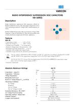
VARICON RADIO INTERFERENCE SUPPRESSION DISC CAPACITORS KM SERIES Description Radio interference suppression KM capacitors offered by KEKO VARICON cover a wide capacitance range from 1 nF to 22 nF, operating at ratedAC voltages 300 V and at frequency of 50 Hz. KEKO VARICON presently offers two branches of Type 2 KM capacitors : Class X1 and Class Y2. They are successfully used in radio interference suppression for home appliances. File No. 5883.11-4670-0011/31WCJ F35/KIL for KM -Y2 capacitors according to standard EN 132400 and IEC 60384-14 for capacitance range from 1 nF to 10 nF for rated voltage...
Open the catalog to page 5
Device Ratings and Characteristics Radio Interference Suppression Disc Capacitors - Class Y2 C Impedance Frequency Characteristics
Open the catalog to page 6
Safety ceramic disc KZ capacitors are intended for galvanic separation of mains and conductive parts that might be touched, i.e. antenna inputs in radio and TV sets. They are ideal for line by-pass, antenna coupling and across-theline applications, especially for the circuits exposed to danger of electric shock. These capacitors meet safety rules applicable to electronic apparatus and associated fittings for domestic or similar general use, connected to mains according to EN 132 400. KZ capacitors offered by KEKO VARICON cover capacitance range from 330 pF to 4700 pF, operating at AC rated voltages...
Open the catalog to page 7
Device Ratings and Characteristics a Safety Disc Capacitors - KZL Class Y2, X1 tan d Impedance Frequency Characteristics
Open the catalog to page 8
HIGH VOLTAGE CERAMIC DISC CAPACITORS High voltage ceramic Type 2 disc capacitors cover cpacitance range from 330 pF to 10 nF operating at voltages from 1 to 6 These capacitors utilize high dielectric constant (K> 8000) ferroelectric formulations based on barium titanate. They exhibit markedly nonlinear temperature characteristics, significant dependence on voltage and frequency and predictable decay of capacitance with time. Such capacitors are suited for by-pass, coupling and filtering applications, where Q, high insulation resistance and stability of capacitance characteristics are not of major...
Open the catalog to page 9
Device Ratings and Characteristics High Voltage Ceramic Disc Capacitors KV C
Open the catalog to page 10
VARICON Lead Styles
Open the catalog to page 11
Series Name Capacitor Class Capacitance Value = 1 nF Rated Voltage Capacitor Class Approvals Capacitance Value = 10 nF Rated Voltage Series Name For Model Size = 9 mm KEKO KM 2n2 300~Y2 KEKO - Tradename KM - Series Name 2n2 - Capacitance Value = 2,2 nF 300~ - Rated Voltage Y2 - Capacitor Class KM Series For Model Size < 9 mm KM 1n0 300~Y2 Capacitor Class Capacitance Value = 1 nF Rated Voltage Series Name Capacitor Class Approvals Capacitance Value = 3,3 nF Rated Voltage Tradename Series Name For Model Size = 9 mm KEKO KZL 1n5 300~Y2 KEKO - Tradename KZL - Series Name 1n5 - Capacitance Value =...
Open the catalog to page 12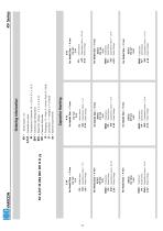
Capacitance Value = 10 nF Rated Voltage Series Name Tradename Series Name Capacitance Value = 3,3 nF Rated Voltage For Model Size = 9 mm KEKO KV 1n5 4 kV KEKO - Tradename KV - Series Name 1n5 - Capacitance Value = 1,5 nF 4 kV - Rated Voltage For Model Size = 9 mm KEKO KV 2n2 2 kV KEKO - Tradename KV - Series Name 2n2 - Capacitance Value = 2,2 nF 2 kV - Rated Voltage Capacitor Marking - Series Name : KV - Capacitance value - Capacitance Tolerance :M = ± 20 %, K = ± 10 % - Ceramic type Designation - Rated DC Voltage : 1, 2, 3, 4, 5, 6 kV - Capacitor Diameter - Packaging : R = Reel, A = Ammo Pack,...
Open the catalog to page 13
Tape & Reel Specification Conforms to IEC Publication 286-2 Ed.3 : 2008-03 Carrier tape width Hold down tape width Sprocket hole position Distance between the upper edges of the carrier tape and hold-down tape Total tape thickness Tape thickness Pitch of component Feed hole pitch Feed hole center to pitch Lead Spacing Component alignment Component alignment Wire diameter Feed hole diameter Height from tape center to comp. base Seating plane height Component height Protrusion - cut out Protrusion - cut off
Open the catalog to page 14
Packaging Reel Ammo pack
Open the catalog to page 15
VARICON Assembly Recommendations for TH Components Very often before soldering of through-hole component its leads are being bent. It is important not to damage the component during lead bending. Typical damage produced during bending are cracks in epoxy pants, which can lead to increased humidity sensitivity of component and consequentially to its shorter life time. In order to avoid epoxy pants damage it is necessary to : -fix the most sensitive point (epoxy pants) of component body -bend wire at least 2 mm below the end of epoxy pants Another potential damage of the component which can lead...
Open the catalog to page 16All Keko Varicon catalogs and technical brochures
 TUBE ZnO VARISTOR
2 Pages
 Product catalogue
98 Pages
 C3V series
2 Pages
 Catalogue - PROTECTIVE DEVICES
18 Pages
 varicons - 2008/2009
32 Pages
 varistors - 2008/2009
40 Pages
 Catalogues 2008 - 2009
4 Pages

