
- Catalogs
- Keithley Instruments
- Switching Handbook: A Guide to Signal Switching in Automated Test


Switching Handbook: A Guide to Signal Switching in Automated Test

Switching Handbook: A Guide to Signal Switching in Automated Test
The Keithley Switching Handbook, 6th Edition, is a detailed guide on signal switching in automated test systems, focusing on the role of relay switching in connecting devices to sources and measurement instruments. It highlights the need for flexibility to handle various signals and tests.
The Switching Function
This section explains the concept of switching in test systems and its impact on performance. It describes ideal switch characteristics and practical limitations, and emphasizes understanding relay configurations like pole, throw, and form for effective system design.
Switching Components
This section explores different types of switching elements and relays, detailing their applications and specifications.
Specifications and Models
It provides detailed specifications for relay and card models, including physical implementation and equivalent circuit models, crucial for understanding technical parameters affecting system design and performance.
Issues in Switch System Design
This section discusses key design considerations such as calculating uncertainties, switching speed, and differences between cold and hot switching. It introduces advanced concepts like TSP™ and TSP-Link™ for better system integration.
Switch Considerations by Signal Type
Switching considerations are categorized by signal types, including voltage, current, resistance, RF, and digital signals, with guidelines for optimizing performance for each type.
Hardware Implementation
Practical aspects of hardware implementation are covered, including connections, wiring, cabling, shielding, grounding, and troubleshooting, essential for reliable system operation.
Applications
This section explores various applications of switching systems, such as battery testing and capacitor leakage measurements, with specific examples and methodologies.
Appendices
The appendices offer a glossary of terms, selector guides for switch cards and modules, and safety considerations, providing additional resources for users.
Matrix Switching
Matrix switch configuration allows multiple inputs to connect to multiple outputs, useful for connecting several signal sources to a multipin device. It describes matrix size as M rows by N columns and highlights considerations like bandwidth and isolation.
Matrix Expansion
A matrix can be expanded by joining rows and/or columns of several cards, enhancing flexibility and capacity.
Isolated Switching
Isolated switching involves individual relays with no connections between them, used in power and control applications for different voltage levels.
RF Switching: Cascade, Tree, and Matrix Switching
RF signals require special considerations like insertion loss and crosstalk. Different configurations like cascade, tree, and matrix switching offer varying levels of isolation and connection paths.
Switching Hardware Options
Considerations for selecting switching hardware include signal types, configuration, number of switch points, and cost. Options range from stand-alone scanner mainframes to plug-in data acquisition boards, each with specific advantages.
Catalog excerpts

Switching Handbook A Guide to Signal Switching in Automated Test Systems Specifications are subject to change without notice. All Keithley trademarks and trade names are the property of Keithley Instruments, Inc. All other trademarks and trade names are the property of their respective companies. A G RE ATER ME A S U R E OF CO N F I D E N C E Keithley Instruments, Inc. Corporate Headquarters • 28775 Aurora Road • Cleveland, Ohio 44139 • 440-248-0400 • Fax: 440-248-6168 1-888-KEITHLEY (534-8453) www.keithley.com © Copyright 2008 Keithley Instruments, Inc. Printed in the U.S.A.
Open the catalog to page 1
“To get a free electronic version of this book, visit Keithley’s Knowledge Center web page.” a g r e at e r m e a s u r e o f c o n f i d e n c e
Open the catalog to page 2
Switching Handbook A Guide to Signal Switching in Automated Test Systems
Open the catalog to page 3
Keithley appreciates the assistance and diligence of Dale Cigoy, Senior Applications Engineer, and Jerry Janesch, Business Development Manager—Multi-Application Products, who contributed to and reviewed the content of this edition of the handbook.
Open the catalog to page 4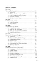
Introduction . . . . . . . . . . . . . . . . . . . . . . . . . . . . . . . . . . . . . . . . . 1-2 Effects of Switching on System Performance . . . . . . . . . . . . . . 1-2 Switch Configurations and Conventions . . . . . . . . . . . . . . . . . . 1-3 Switching Topologies . . . . . . . . . . . . . . . . . . . . . . . . . . . . . . . . . . 1-4 Switching Hardware Options . . . . . . . . . . . . . . . . . . . . . . . . . . . 1-16 Switching Components . . . . . . . . . . . . . . . . . . . . . . . . . . . . . . . . . . 2-1 2.1 Switching Elements . . . . . . . . . . . . . . . . . . . . . . . . . ....
Open the catalog to page 5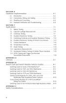
Introduction . . . . . . . . . . . . . . . . . . . . . . . . . . . . . . . . . . . . . . . . . 6-2 Connections, Wiring, and Cabling . . . . . . . . . . . . . . . . . . . . . . . 6-2 Shielding and Grounding . . . . . . . . . . . . . . . . . . . . . . . . . . . . . . 6-6 Hardware Verification and Troubleshooting . . . . . . . . . . . . . . . 6-8 Battery Testing . . . . . . . . . . . . . . . . . . . . . . . . . . . . . . . . . . . . . . . 7-2 Capacitor Leakage Measurements . . . . . . . . . . . . . . . . . . . . . . . 7-4 Continuity Testing . . . . . . . . . . . . . . . . . . . . . . . . . . . ....
Open the catalog to page 6
S w itchi n g H a n db o o k , S i x th E diti o n A Guide to Signal S witching in Automated T est S y stems
Open the catalog to page 7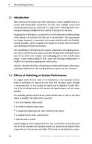
1.1 Introduction Many electronic test systems use relay switching to connect multiple devices to sources and measurement instruments. In some cases, mul iple sources and t measuring instruments are connected to a single device. Switching allows automating the testing of multiple devices, thereby reducing error and costs. Designing the switching for an automated test system demands an understanding of the signals to be switched and the tests to be perormed. Test requirements f can change frequently, so automated test systems should provide the flexibility needed to handle a variety of sig als....
Open the catalog to page 8
frame that electronically controls the opening and closing of the relays. Therefore, when calculating the overall system accuracy, the engineer must include not only the effects of the switch itself, but all the switching hardware in the system. For example, the offset current of the relays and the leakage resis ance of the t boards, connectors, and cables may degrade the integrity of high impedance applications. Contact potential and contact resis ance of the relays can reduce t the accuracy of low voltage and low resis ance circuits. Switches may reduce t the bandwidth of high frequency...
Open the catalog to page 9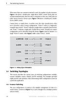
When more than one common terminal is used, the number of poles increases. Figure 1-1c shows a double-pole, single-throw (DPST) switch. Both poles are actuated simultaneously when the relay is ener ized. In this case, both poles are g either always closed or always open. Figure 1-1d shows a double-pole, doublethrow (DPDT) switch. Contact form, or simply form, is another term that relay manufac urers often t use to describe a relay’s contact configuration. “Form A” refers to a single-pole, normally-open switch. “Form B” indicates a single-throw, normally-closed switch, and “Form C” indicates...
Open the catalog to page 10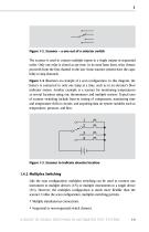
Figure 1-2. Scanner – a one out of n selector switch The scanner is used to connect multiple inputs to a single output in sequential order. Only one relay is closed at any time. In its most basic form, relay closure proceeds from the first channel to the last. Some scanner systems have the capability to skip channels. illustrates an example of a scan configuration. In this diagram, the battery is connected to only one lamp at a time, such as in an elevator’s floor indicator system. Another example is a scanner for monitoring temperatures at several locations using one thermometer and multiple...
Open the catalog to page 11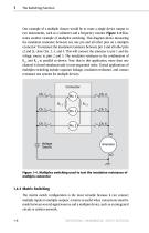
One example of a multiple closure would be to route a single device output to two instruments, such as a voltmeter and a frequency counter. Figure 1-4 illustrates another example of multiplex switching. This diagram shows measuring the insulation resistance between any one pin and all other pins on a multipin connector. To measure the insulation resistance between pin 1 and all other pins (2 and 3), close Chs. 2, 3, and 4. This will connect the ammeter to pin 1 and the voltage source to pins 2 and 3. The insulation resistance is the combination of R1-2 and R1-3 in parallel as shown. Note that...
Open the catalog to page 12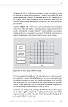
Using a matrix switch card allows connecting any input to any output by closing the switch at the intersection (crosspoint) of a given row and column. The most common terminology to describe the matrix size is M rows by N columns (MxN). For example, a 4x10 matrix switch card, such as the Keithley Model 7012, has four rows and ten columns. Matrix switch cards generally have two or three poles As shown in Figure 1-5, a 5VDC source can be connected to any two terminals of the device under test (DUT). A function generator supplies pulses between another two terminals. Operation of the DUT can be...
Open the catalog to page 13All Keithley Instruments catalogs and technical brochures
 6220-6221
5 Pages
 2520
25208 Pages
 2606B
2606B13 Pages
 2601B
2601B20 Pages
 AFG1000 Series
13 Pages
 AFG31000 Series Datasheet
22 Pages
 2182A Nanovoltmeter
11 Pages
 4200A-SCS Parameter Analyzer
45 Pages
 2461 SourceMeter® SMU Instrument
16 Pages
 2460 SourceMeter® SMU Instrument
14 Pages
 MDO4000C Series Datasheet
43 Pages
 4200A-SCS Parameter Analyzer
45 Pages






Archived catalogs
 6 Series B MSO
69 Pages
 Isolated Measurement Systems
8 Pages
 TBS1000B-EDU Series
14 Pages
 3 Series MDO
36 Pages
 4 Series MSO
40 Pages
 TSG4100A Series
24 Pages
 2461-EC Graphical Potentiostat
16 Pages
 2460-EC Graphical Potentiostats
15 Pages
 2450-EC Graphical Potentiostat
15 Pages
 RTPA2A
6 Pages
 TPA-N-PRE Datasheet
4 Pages
 DPO4PWR·MDO3PWR Datasheet
6 Pages
 DPO4LMT/MDO3LMT Datasheet
6 Pages
 DPO7000 Series Datasheet
28 Pages
 SourceXpress® Datasheet
4 Pages
 10G-KR Datasheet
8 Pages
 DPO70000SX Series Datasheet
46 Pages
 AWG4000 Series Datasheet
20 Pages
 TLA6400 Series Datasheet
14 Pages
 Potentiostats 2450-EC
8 Pages
 2013 Keithley product catalog
403 Pages
 Nanotechnology Measurement
13 Pages
 Semiconductor Device Test
11 Pages
 Series 2400 SourceMeter®Family
16 Pages
 8 Series Sampling Oscilloscope
14 Pages
 Multimeter/Switch System
1 Page




- Power supply unit
- DC power supply
- AC/DC power supply
- Management software solution
- Analysis software solution
- Real-time software
- Windows software
- Single-output power supply
- Portable tester
- Measurement software
- Interface software
- Digital tester
- Compact power supply
- Visualization software solution
- Tabletop power supply
- Automated software
- Automatic test kit
- Digital gauge