Serial Triggering and Analysis Application Modules AERO • AUDIO • AUTO • AUTOMAX • COMP • EMBD • FLEX • USB • ENET Datasheet
1 /
32Pages
Catalog excerpts
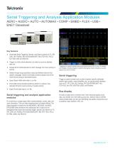
Serial Triggering and Analysis Application Modules AERO • AUDIO • AUTO • AUTOMAX • COMP • EMBD • FLEX • USB • ENET Datasheet Key features Automated Serial Triggering, Decode, and Search options for I2C, SPI, CAN, LIN, FlexRay, RS-232/422/485/UART, MIL-STD-1553, I2S/LJ/ RJ/T DM, USB, and Ethernet. Trigger on all the critical elements of a serial bus such as address, data, etc. Decode all the critical elements of each message. No more counting 1s and 0s! Triggering on a specific transmit data packet going across an RS-232 bus. A complete set of triggers, including triggers for specific serial packet content, ensures you quickly capture your event of interest. Search through long acquisitions using user-defined criteria to find specific messages. Search mark table provides a tabular view of the events found during an automated search. Serial triggering Export Search Mark table data to .csv file. Event table shows decoded serial bus activity in a tabular, timestamped format for quick summary of system activity. Export Event table data to .csv file. Serial triggering and analysis application modules On a serial bus, a single signal often includes address, control, data, and clock information. This can make isolating events of interest difficult. The Serial Application modules for the MDO4000C, MDO3000, and MSO/ DPO2000B Series transform the oscilloscope into a robust tool for debugging serial buses with automatic trigger, decode, and search for I2C, SPI, CAN, LIN, FlexRay, RS-232/422/485/UART, MIL-STD-1553, I2S/LJ/ RJ/TDM, USB2, and Ethernet. Trigger on packet content such as start of packet, specific addresses, specific data content, unique identifiers, etc. on popular serial interfaces such as I2C, SPI, CAN, LIN, FlexRay, RS-232/422/485/UART, MILSTD-1553, and I2S/LJ/RJ/TDM, USB2, and Ethernet. Bus display Provides a higher-level, combined view of the individual signals (clock, data, chip enable, etc.) that make up your bus, making it easy to identify where packets begin and end and identifying sub-packet components such as address, data, identifier, CRC, etc.
Open the catalog to page 1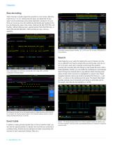
Datasheet Bus decoding Tired of having to visually inspect the waveform to count clocks, determine if each bit is a 1 or a 0, combine bits into bytes, and determine the hex value? Let the oscilloscope with a Serial Application module do it for you! Once you’ve set up a bus, the oscilloscope will decode each packet on the bus, and display the value in hex, binary, decimal (LIN, MIL-STD-1553, and FlexRay, USB and Ethernet only), signed decimal (I2S/LJ/RJ/TDM only), or ASCII (RS-232/422/485/UART, USB and Ethernet only) in the bus waveform. Event table showing decoded Identifier, DLC, DATA, and...
Open the catalog to page 2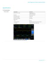
Serial Triggering and Analysis Application Modules Specifications I²C Characteristics Bus setup options Sources (Clock and Data) Analog channels 1-4 Digital channels D0-D15 Per-channel thresholds Recommended probing Single ended Decode formats available Simultaneous display of bus and logic waveforms Event table Decoded packet data in a tabular view I2C bus setup, showing selection of bus display modes.
Open the catalog to page 3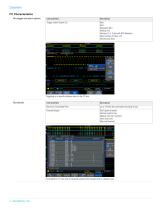
Datasheet I²C Characteristics Bus trigger and search options Trigger and/or Search On Start Stop Repeated Start Missing Ack Address (7 or 10 bit) with R/W Selection Data (number of bytes 1-5) Address and Data Triggering on a specific address value on the I2C bus. Bus decode Maximum Clock/Data Rate Decode Display Start (green bracket) Address (yellow box) Missing Ack (red ! symbol) Data (cyan box) Stop (red bracket) Event table for I2C bus with all captured packets time stamped and in a tabular view.
Open the catalog to page 4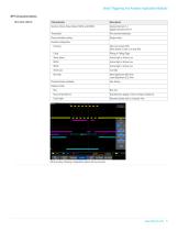
Serial Triggering and Analysis Application Modules SPI Characteristics Bus setup options Sources (Clock, Slave Select, MOSI, and MISO) Analog channels 1-4 Digital channels D0-D15 Per-channel thresholds Recommended probing Single ended Decode configuration Framing Idle Time (2-wire SPI) Slave Select (3-wire or 4-wire SPI) Rising or Falling Edge Slave select Active High or Active Low Active High or Active Low Active High or Active Low Word size Most Significant (MS) First Least Significant (LS) First Decode formats available Simultaneous display of bus and logic waveforms Event table Decoded...
Open the catalog to page 5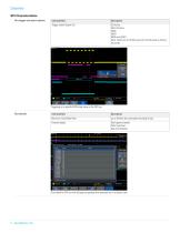
Datasheet SPI Characteristics Bus trigger and search options Trigger and/or Search On SS Active Start of Frame MOSI MISO MOSI and MISO Data: maximum of 128 bits (up to four 32-bit words or 32 fourbit words) Triggering on a specific MOSI data value on the SPI bus. Bus decode Maximum Clock/Data Rate Decode display Start (green bracket) Data (cyan box) Stop (red bracket) Event table for SPI bus with all captured packets time stamped and in a tabular view.
Open the catalog to page 6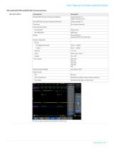
Serial Triggering and Analysis Application Modules RS-232/UART/RS-422/RS-485 Characteristics Bus setup options RS-232/UART Sources (Transmit and Receive) Analog channels 1-4 Digital channels D0-D15 RS-422/RS-485 Sources (Transmit and Receive) Per-channel thresholds Single ended Normal (RS-232) Inverted (UART, RS-422/RS-485) Decode configuration Bit rate Pre-defined list of rates Data bits Decode formats available Simultaneous display of bus and logic waveforms Event table Decoded packet data in a tabular view RS-232 bus setup, showing bit rate options for RS-232 bus.
Open the catalog to page 7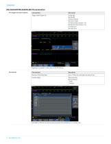
Datasheet RS-232/UART/RS-422/RS-485 Characteristics Bus trigger and search options Trigger and/or Search On Tx Start Bit Rx Start Bit Tx End of Packet Rx End of Packet Tx Data (number of bytes 1-10) Rx Data (number of bytes 1-10) Tx Parity Error Rx Parity Error Triggering on a specific Tx data value on the RS-232 bus. Bus decode Maximum Clock/Data Rate Decode display Data (cyan box) Errors (red box) - Parity - Framing Event table for RS-232 bus with all captured packets time stamped and in a tabular view.
Open the catalog to page 8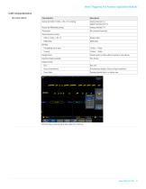
Serial Triggering and Analysis Application Modules CAN Characteristics Bus setup options Source for CAN_H, CAN_L, Rx, or Tx probing Analog channels 1-4 Digital channels D0-D15 Source for differential probing Per-channel thresholds Recommended probing CAN_H, CAN_L, Rx, Tx Single ended Bit Rate Pre-defined list of rates Sample Point Position at 5% to 95% within bit period or unit interval Decode formats available Simultaneous display of bus and logic waveforms Event table Decoded packet data in a tabular view CAN bus setup, showing signal type options for CAN bus.
Open the catalog to page 9All Keithley Instruments catalogs and technical brochures
-
6220-6221
5 Pages
-
6482
3 Pages
-
2520
8 Pages
-
2606B
13 Pages
-
2601B
20 Pages
-
AFG1000 Series
13 Pages
-
AFG31000 Series Datasheet
22 Pages
-
2182A Nanovoltmeter
6 Pages
-
6 Series B MSO
69 Pages
-
Isolated Measurement Systems
8 Pages
-
TBS1000B-EDU Series
14 Pages
-
3 Series MDO
36 Pages
-
4 Series MSO
40 Pages
-
TSG4100A Series
24 Pages
-
2461-EC Graphical Potentiostat
16 Pages
-
2460-EC Graphical Potentiostats
15 Pages
-
2450-EC Graphical Potentiostat
15 Pages
-
4200A-SCS Parameter Analyzer
45 Pages
-
MDO4000C Series Datasheet
43 Pages
-
RTPA2A
6 Pages
-
TPA-N-PRE Datasheet
4 Pages
-
DPO4PWR·MDO3PWR Datasheet
6 Pages
-
DPO4LMT/MDO3LMT Datasheet
6 Pages
-
DPO7000 Series Datasheet
28 Pages
-
SourceXpress® Datasheet
4 Pages
-
10G-KR Datasheet
8 Pages
-
DPO70000SX Series Datasheet
46 Pages
-
AWG4000 Series Datasheet
20 Pages
-
TLA6400 Series Datasheet
14 Pages
-
Potentiostats 2450-EC
8 Pages
-
4200-SCS
16 Pages
-
2013 Keithley product catalog
403 Pages
-
Nanotechnology Measurement
13 Pages
-
Semiconductor Device Test
11 Pages
-
Series 2400 SourceMeter®Family
16 Pages
Archived catalogs
-
8 Series Sampling Oscilloscope
14 Pages
-
Multimeter/Switch System
1 Pages


