


2520

2520
- Integrated solution for in-process LIV production testing at chip or bar level.
- Programmable pulse on time from 500ns to 5ms, up to 4% duty cycle.
- Pulse capability up to 5A, DC capability up to 1A.
- 14-bit measurement accuracy on three channels (VF, front photodiode, back photodiode).
- IEEE-488 and RS-232 interfaces for system integration.
Catalog excerpts

2520 Pulsed Laser Diode Test System Datasheet Key Performance Specifications • Simplifies laser diode LIV testing prior to packaging or active temperature control • Integrated solution for in-process LIV production testing of laser diodes at the chip or bar level • Sweep can be programmed to stop on optical power limit • Combines high accuracy source and measure capabilities for pulsed and DC testing • Synchronized DSP based measurement channels ensure highly accurate light intensity and voltage measurements • Programmable pulse on time from 500ns to 5ms up to 4% duty cycle • Pulse capability up to 5A, DC capability up to 1A • 14-bit measurement accuracy on three measurement channels (VF, front photodiode, back photodiode) • Measurement algorithm increases the pulse measurement’s signal-tonoise ratio Remote Electrical Test Head included • Up to 1000-point sweep stored in buffer memory eliminates GPIB traffic during test, increasing throughput • Digital I/O binning and handling operations • IEEE-488 and RS -232 interfaces The Model 2520 Pulsed Laser Diode Test System is an integrated, synchronized system for testing laser diodes early in the manufacturing process, when proper temperature control cannot be easily achieved. The Model 2520 provides all sourcing and measurement capabilities needed for pulsed and continuous LIV (light-currentvoltage) testing of laser diodes in one compact, half-rack instrument. The tight synchronization of source and measure capabilities ensures high measurement accuracy, even when testing with pulse widths as short as 500ns. Applications Production testing of: • Telecommunication laser diodes • Optical storage read/write head laser diodes • Vertical Cavity Surface-Emitting Lasers (VCSELs) • Thermal impedance
Open the catalog to page 1
LIV Test Capability The Model 2520 can perform pulsed LIV testing up to 5A and continuous LIV testing up to 1A. Its pulsed testing capability makes it suitable for testing a broad range of laser diodes, including the pump laser designs for Raman amplifiers. The instrument’s ability to perform both DC and pulsed LIV sweeps on the same device simplifies analyzing the impact of thermal transients on the LIV characteristics of the laser diode. Maximize Throughput and Eliminate Production Bottlenecks By working in cooperation with leading laser diode manufacturers, Keithley designed the Model 2520...
Open the catalog to page 2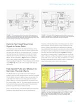
2520 Pulsed Laser Diode Test System Model 2520 High-Speed Current to Voltage Converter Sequencing and Signal Analysis Computer High-Speed Multi-Channel Oscilloscope High-Speed Current to Voltage Converter Front Facet Detector Pulse Source High-Speed Current to Voltage Converter Remote Test Head Laser Diode Chip or Bar Rear Facet Detector Voltage Measure Sequencing and Signal Analysis DSP High-Speed Multi-Channel Digitizer High-Speed Current to Voltage Converter Laser Diode Chip or Bar Rear Facet Detector FIGURE 1. This schematic reflects the current testing practices of major laser diode manufacturers....
Open the catalog to page 3
A laser diode’s material make-up, design, and small size make it extremely sensitive to temperature increases and electrostatic discharges (ESDs). To prevent damage, prior to the start of the test and after test completion, the Model 2520 shorts the DUT to prevent transients from destroying the device. The instrument’s 500 nanosecond pulse and measure test cycle minimizes device heating during test, especially when a short duty cycle is used. The Model 2520 comes with all the interconnecting cables required for the main instrument and the remote test head. Production test practices vary widely...
Open the catalog to page 4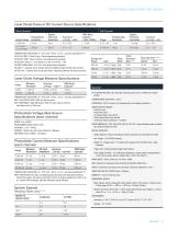
2520 Pulsed Laser Diode Test System Laser Diode Pulse or DC Current Source Specifications Drive Current TEMPERATURE COEFFICIENT (0°-18°C & 28°-50°C): ±(0.15 x accuracy specification)/^. PULSE ON TIME19: 500ns to 5ms, 100ns programming resolution. PULSE OFF TIME19: 20ps to 500ms, 10ps programming resolution. PULSE DUTY CYCLE20- 21: 0 to 99.6% for 11.0A; 0 to 4% for >1.0A. VOLTAGE COMPLIANCE: 3V to 10V, 10mV programming resolution5. POLARITY: 1 quadrant source, polarity reversal available through internal relay inversion. OUTPUT OFF: <200mfi short across laser diode; measured at Remote Test Head...
Open the catalog to page 5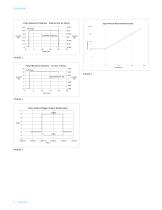
Pulse Waveform Flatness - 500mA into 20 Ohms FIGURE 1 Pulse Waveform Flatness - 5A into 2 Ohms
Open the catalog to page 6
2520 Pulsed Laser Diode Test System Averaging Filter Setting 2. If V Duty Cycle ■ I exceeds 0.2, accuracy specifications must be derated with an additional error term as follows: 500mA Range: ±0.1% rdg. ■ Vd ■ I where: I = current setting D = duty cycle This derating must also be applied for a period equal to the time that TD ■ I was >0.2. 3. Not including overshoot and setting time. 4. Pulse mode only. 5. Output: 500mA DC on 500mA range and 1A DC on 5A range. 6. Refer to Model 2520 Service Manual for test setup of current accuracy. 7. Figures 1 and 2 are typical pulse outputs into resistive...
Open the catalog to page 7
Find more valuable resources at TEK.COM Copyright © Tektronix. All rights reserved. Tektronix products are covered by U.S. and foreign patents, issued and pending. Information in this publication supersedes that in all previously published material. Specification and price change privileges reserved. TEKTRONIX and TEK are registered trademarks of Tektronix, Inc. All other trade names referenced are the service marks, trademarks or registered trademarks of their respective companies. 09/19 EA 1KW-61621-0 European toll-free number. If not accessible, call: +41 52 675 3777
Open the catalog to page 8All Keithley Instruments catalogs and technical brochures
 6220-6221
5 Pages
 2606B
2606B13 Pages
 2601B
2601B20 Pages
 AFG1000 Series
13 Pages
 AFG31000 Series Datasheet
22 Pages
 2182A Nanovoltmeter
11 Pages
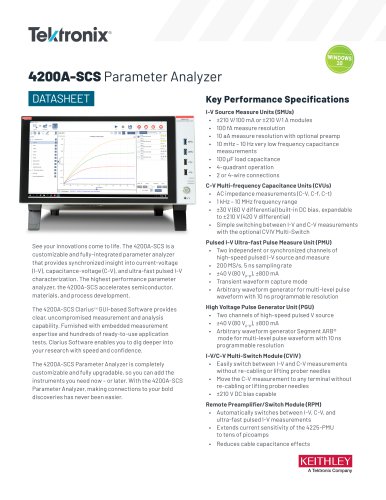 4200A-SCS Parameter Analyzer
45 Pages
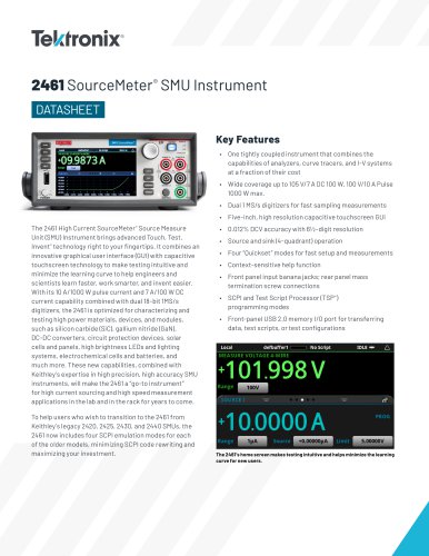 2461 SourceMeter® SMU Instrument
16 Pages
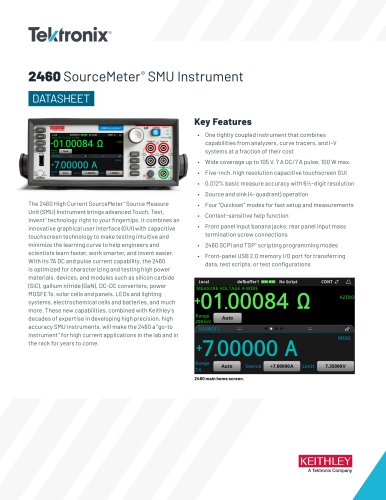 2460 SourceMeter® SMU Instrument
14 Pages
 MDO4000C Series Datasheet
43 Pages
 4200A-SCS Parameter Analyzer
45 Pages








Archived catalogs
 6 Series B MSO
69 Pages
 Isolated Measurement Systems
8 Pages
 TBS1000B-EDU Series
14 Pages
 3 Series MDO
36 Pages
 4 Series MSO
40 Pages
 TSG4100A Series
24 Pages
 2461-EC Graphical Potentiostat
16 Pages
 2460-EC Graphical Potentiostats
15 Pages
 2450-EC Graphical Potentiostat
15 Pages
 RTPA2A
6 Pages
 TPA-N-PRE Datasheet
4 Pages
 DPO4PWR·MDO3PWR Datasheet
6 Pages
 DPO4LMT/MDO3LMT Datasheet
6 Pages
 DPO7000 Series Datasheet
28 Pages
 SourceXpress® Datasheet
4 Pages
 10G-KR Datasheet
8 Pages
 DPO70000SX Series Datasheet
46 Pages
 AWG4000 Series Datasheet
20 Pages
 TLA6400 Series Datasheet
14 Pages
 Potentiostats 2450-EC
8 Pages
 2013 Keithley product catalog
403 Pages
 Nanotechnology Measurement
13 Pages
 Semiconductor Device Test
11 Pages
 Series 2400 SourceMeter®Family
16 Pages
 8 Series Sampling Oscilloscope
14 Pages
 Multimeter/Switch System
1 Page




- Power supply unit
- DC power supply
- AC/DC power supply
- Measuring device
- Management software solution
- Analysis software solution
- Real-time software
- Windows software
- Single-output power supply
- Portable tester
- Measurement software
- Interface software
- Digital tester
- Compact power supply
- Visualization software solution
- Generator
- Tabletop power supply
- Automated software
- Automatic test kit
- Digital gauge