
Catalog excerpts

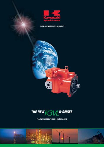
Precision Machinery Company Swash-plate Axial Piston Pump
Open the catalog to page 1
CONTENTS Applications / Product Usage Safety Precautions Handling Precautions Conversion Factors, Formula and Definition General Description and Features 2-4. adial Loading Capacity R 2-5. unctional Description of Regulator F 2-6. orque Limiter Settings T 3-7. Electric & Hydraulic Displacement Control 3-8. Unloading & Proportional Pressure Control Installation 3-9. Power Shift Control Installation
Open the catalog to page 2
Applications/Product Usage The following must be taken into consideration before use. 1. The operating condition of the products shown in this catalog varies depending upon each application. Therefore, the product suitability must be judged by the designer of the hydraulic system and/ or the person who finalizes the technical specifications of the machine after analysis and testing. The product specification shall be determined based on the latest catalog and technical documents. The system must be designed taking into account the possibility of machine failure to ensure that all safety,...
Open the catalog to page 3
Safety Precautions Before using the product, you MUST read this catalog and MUST fully understand how to use the product. To use the product safely, you MUST carefully read all Warnings and Cautions in this catalog. 1. Cautions related to operation - Use the personal protective equipment to prevent injury when the product is in operation. - Some components are heavy. Handle the product carefully not to hurt your hands and lower back. - Do not step on, hit or drop , or apply strong force to the product, as these actions may cause operation failure, product damage, or oil leakage. - Wipe off...
Open the catalog to page 4
Handling Precautions 1. Operating Fluid and Temperature Range 2. Filtration and Contamination Control Values shown in this catalog are based upon using mineral oil based anti-wear hydraulic fluid. To ensure optimal performance use of mineral oil based anti-wear hydraulic fluid is recommended. The most important means to prevent premature damage to the pump and associated equipment and to extend its working life, is to ensure that hydraulic fluid contamination control of the system is working effectively. 2) Viscosity and temperature range This begins by ensuring that at the time of...
Open the catalog to page 5
3. Drive Shaft Coupling Alignment between the prime mover and the pump shaft should be within 0.05 mm TIR*. In case the pump is directly coupled to the engine flywheel, use a flexible coupling. *TIR = Total Indicator Reading dial gauge (reading a) δ =a/2 0.025mm dial gauge (reading b) α=SIN-1 (b/D) 0.2° 4. Oil Filling and Air Bleeding 1) Pump case filling Be sure to fill the pump casing with oil through the drain port, filling only the suction line with oil is totally in-sufficient. The pump contains bearings and high-speed sliding parts including pistons with shoes and a spherical bush...
Open the catalog to page 6
5. Drain Piping 1) Installation of drain line It is the preferred option to mount the pump with the case drain piping initially rising above the pump before continuing to the tank. Do not connect the drain line to the inlet line. Cautions A) Inlet and drain pipes must be immersed by 200 mm minimum from the lowest level under operating conditions. B) Height from the oil level to the centre of the shaft must be within 1 meter maximum. C) The oil in the pump case must be refilled when the pump has not been operated for one month or longer. The uppermost drain port should be used and the drain...
Open the catalog to page 7
7. Mounting the Pump Vertically (shaft up) Note: Both the Tair and one case drain port must be used. For applications requiring vertical installation (shaft up) please remove the Tair bleed plug and connect piping as shown in the illustration below. When installing the pump in the tank and submerged in the oil, open the drain port and Tair bleed port to provide adequate lubrication to the internal components. See illustration [A]. The oil level in the tank should be higher than the pump-mounting flange as shown in illustration [A] below. If the oil level in the tank is lower than the pump...
Open the catalog to page 8
Conversion Factors, Formula and Definition Conversion Factors Formula Formula Metric system Output flow Input torque Input power Imperial system L/min = Pump delivery pressure = Pump suction pressure = Load sensing pressure = Pump case pressure = Power shift pressure = Maximum input torque = Pump volumetric efficiency = Pump mechanical efficiency
Open the catalog to page 9
K3VL Series Swash-plate Axial Piston Pump General Descriptions The K3VL series Swash Plate Type Axial Piston Pumps 320 bar continuous pressure rating are designed to satisfy the marine, mobile and industrial markets where a medium/high pressure variable High overall effciency (>90% peak) displacement pump is required. K3VL pumps are available in nominal displacements ranging from 28 to 200 cm3/rev with various pressure, Exceptional self priming capability SAE and ISO mounting and shaft torque limiter, and combination of load sensing control Excellent reliability and very long service life...
Open the catalog to page 11
Ordering Code Preferred product range K3VL Series, Variable Displacement, Axial Piston, Open Loop Pump NOT AVAILABLE IN COUNTER CLOCKWISE PLEASE CONTACT KPM UK - 2. Pump Size Maximum Displacement 4. Hydraulic Fluid Type - Mineral Oil, Nitrile seal + Viton Shaft Seal Viton Seal Throughout Water Glycol (Nitrile Seal & Nitrile Shaft Seal) *1 Open Circuit 6. Through Drive & Porting 0 A SAE-A Through Drive, Side Ported Without Through Drive SAE-B Through Drive, Side Ported SAE-BB Through Drive, Side Ported SAE-C, 2 Bolt, Through Drive, Side Ported SAE-C, 4 Bolt, Through Drive, Side Ported...
Open the catalog to page 12
8. Mounting Flange & Shaft K SAE-C Spline & SAE-D Mount SAE-C Spline & SAE-C2 Mount SAE-CC Spline & SAE-C2 Mount SAE-F Spline & SAE-E Mount SAE-B Spline & SAE-B, 2 Bolt Mount SAE-CC Spline & SAE-D, 4 Bolt Mount Metric Threads UNC Thread (Not Available with ‘M’ ISO Key Shaft & Mount) Load Sense + Pressure Cut-Off (With LS Bleed) Load Sense + Pressure Cut-Off (With LS Bleed Blocked) Load Sense & Intergral Unload (Normally Open) Load Sense & Intergral Unload (Normally Closed) Load Sense & Intergral Proportional Relief Load Sense & Intergral Proportional Relief Pressure Cut-Off Pressure Cut-Off...
Open the catalog to page 13All Kawasaki Precision Machinery catalogs and technical brochures
-
 HPB Series
76 Pages
-
 M3X/M3B
35 Pages
-
 HPC Series
37 Pages
-
 HMC Series
43 Pages
-
 K3V/K5V/K7V
8 Pages
-
 HMB Series
92 Pages
-
 PV series
2 Pages
-
 ERU series
2 Pages
-
 HMF Series
72 Pages
-
 M7V / M7X Series
64 Pages
-
 HPC Series
37 Pages
-
 KPM-PV
2 Pages
-
 KDRDE KWE series
2 Pages
-
 KTEM/ KTMS series
2 Pages
-
 K3VL Series
72 Pages
-
 HMF Series
72 Pages
-
 KMP series
2 Pages
-
 ERU series
2 Pages
-
 K7VG
K7VG32 Pages
-
 K8V
K8V36 Pages
-
 K3VLS
K3VLS36 Pages
-
 KLSV 18
24 Pages
-
 KPES
KPES2 Pages
-
 HPC400
4 Pages
-
 hydraulic industriel vehicle
20 Pages
-
 B - Brake Valve
24 Pages
-
 M-Motor
35 Pages
-
 CBD - Counterbalance Valve
6 Pages
-
 M2X/M5X - Slewing motor
19 Pages
-
 Axial Piston Pump Series K3VG
34 Pages
-
 K3VG Series
34 Pages
-
 HMC-capability-brochure
6 Pages
-
 High-Power-HPC-Series-Datasheet
44 Pages


Archived catalogs
-
 HMB
HMB70 Pages
-
 HMC CATALOGUE
60 Pages
-
 Rotary Actuator HR Series
8 Pages
-
 B-motor-catalog-
70 Pages
-
 Datasheet - K3VL B Series
53 Pages
-
 THE K3VLB-SERIES
6 Pages
-
 High Power HPC Series
40 Pages
-
 Axial piston hydraulic motors
35 Pages


