
- Catalogs
- Kawasaki Industrial Equipment
- HMKB/HMKC series

HMKB/HMKC series
1 /32Pages
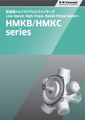
HMKB/HMKC series
1 /32Pages
Catalog excerpts
Powering your potential Low-Speed, High-Trque, Radial Piston Motors
Open the catalog to page 1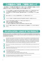
®m=?t}s im. ids. &a« ue ©ffl® cffit>n*«So Although our products are designed on the basis of our profound knowledge and long experience, and manufactured under the strict quality control system, the following must be taken into consideration in actual use. The operating conditions of the products shown in this catalogue vary depending upon each application, and therefore, the decision of the products’ suitability to the system considered must be made by the designer of the hydraulic system and/or the person in charge of determining the specification after making analysis and conducting tests,...
Open the catalog to page 2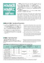
S;£8B£L qTSMSW:*©^ V7y-Fb WcfcWJtfEHU'^ffcdcfc a*SSS©=—XlcEJSa.L'CSl/VJ^'Jo Our low-speed, high-torque, radial piston motor, called Kawasaki Staffa Motor, is extraordinary in performance, reliabilily, output and variety of sizes available. Its characteristics are large displacement per revolution, high torque at low speed, and easy maintenance and operation because of simple construction. We can provide both fixed and variable displacement types in a wide variety of sizes to meet customers’ specific needs. « S'JR»rn erne (somi n-MUT) ■emeu =e-? ^-^ifwa(DjMEi*40Tciu'Ficufc©siB»aiiur<« SUo=E-?$--7.<f:^li)>S©S)t^tf'40°Cm±T?c:'ffiffllC®S...
Open the catalog to page 3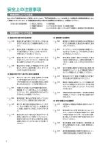
® £ffla±ij£;£ ® JIS B 8265/8266 E^gisOgii ® mmfe © JIS B 8361 ;lE-'>XxAS^©)i§50-®lIlJS^±l5R*II ms)mnte£&mz?z£tfi&M?o ®Aa* Bffl^05ictt*UfcftB»ii+#(c&5 ^ ®or<rc^UoMs^<hurcu,T^or [ttfer&&nifwjmra ©ASM BftrBB^BlE^SBdld: 5SE0SS, B ^ BEBflflEUWJIt^dicyWBfflJluB*^ 8WC<£«fflBUfc±TSHEOT<;3£Wo ®asi BEitJ»Bfflijjftffl^yiyy-rp©3iflE±B ^ &£lc<fcyKffilc&us*©^3^itt^ new cfcaicaai/c <csw. ^tt£'©a nflf*u*^o ©Aa^ BSttBy£<^»»EU«U0:UT?< ^ «SW,a»SnfcttE*B»T?®*\SW *>*K©BHlcS:y S*-0 fi*fio*T«*^tt»FifflB©a5«Etf
Open the catalog to page 4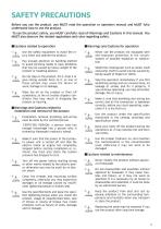
ICautions related to operation IWarnings and Cautions for operation <D Use the safety equipment to avoid the in-caution jury when you operate the product. ©A Pay enough attention on handling method to avoid pinching hands or back problems that may be caused by heavy weight of the product or handling posture. > A Do not step on the product, hit it, drop it or (^0^ give strong outside force to it, as one of these actions may cause the failure of work, damage or oil leakage. ©a Wipe the oil on the product or floor off completely, as the oil creates slippery conditions that may result in dropping...
Open the catalog to page 5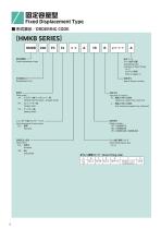
mmFixed Displacement Type JlSitKai/ORDERING CODE Assembling code (Location of drain fitting) A~Z mm*i Special feature number Shaft shape JSSS : Z^'fVlSH'VTtt'Jn-KS) Splined shaft (involute / straight-sided) Parallel shaft Tapered shaft Clockwise viewed from shaft end l ; ttffldcyjarHis Anti-clockwise viewed from shaft end Valve housing with main ports SI : flPP Drain fitting type & size A~G
Open the catalog to page 6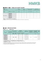
*1 Pressure to which guarantee of performance, functions and service life is applied. Durability is unlimited (except for the bearing life). *2 Pressure which enables operation with no functional problems. Durability and service life are limited. Please consult us for details. *3 Values are mean ones, not guaranteed ones.
Open the catalog to page 7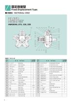
mmFixed Displacement Type8fiB0/SECTIONAL VIEW □BEH/Parts List $1^
Open the catalog to page 10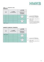
• i®±EH—K/ASSEMBLING CODE (Note) 1: Codes A through F show position of DRAIN FITTING. 2: Figures are shown viewed from the valve end cap.
Open the catalog to page 11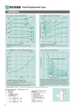
SaElSmS! Fixed Displacement Type The output torque is shown for various speeds and pressure differences. The volumetric efficiency is shown for various speeds and pressure differences. Fig. 2 shows the pressure difference required to drive the shaft at various speeds against zero load. It is important that sufficient inlet pressure given in this graph for each speed is maintained when pumping to prevent cavitation. meraMSisus*-. ernes, nsAii^roaffltBigfPFi-iresni^iSLS^o Fig. 4 shows the shaft creep speed, which is the amount of rotation due to leakage inside the motor when the torque load tries...
Open the catalog to page 12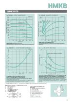
The output torque is shown for various speeds and pressure differences. The volumetric efficiency is shown for various speeds and pressure differences. Fig. 2 shows the pressure difference required to drive the shaft at various speeds against zero load. It is important that sufficient inlet pressure given in this graph for each speed is maintained when pumping to prevent cavitation. Fig. 4 shows the shaft creep speed, which is the amount of rotation due to leakage inside the motor when the torque load tries to rotate the shaft with the outlet port closed. In his case, the motor is quickly rotated...
Open the catalog to page 13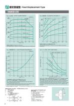
SaElSmS! Fixed Displacement Type The output torque is shown for various speeds and pressure differences. The volumetric efficiency is shown for various speeds and pressure differences. Fig. 4 TUvfm. SHAFT CREEP SPEED mtc. Jifvtfvira-sREiaHa^-xi'EEfi-cfeaBysTo Fig. 2 shows the pressure difference required to drive the shaft at various speeds against zero load. It is important that sufficient inlet pressure given in this graph for each speed is maintained when pumping to prevent cavitation. Fig. 4 shows the shaft creep speed, which is the amount of rotation due to leakage inside the motor when...
Open the catalog to page 14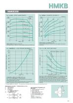
The output torque is shown for various speeds and pressure differences. The volumetric efficiency is shown for various speeds and pressure differences. Fig. 2 shows the pressure difference required to drive the shaft at various speeds against zero load. It is important that sufficient inlet pressure given in this graph for each speed is maintained when pumping to prevent cavitation. LhO0IS±'CffiaIfii'5IS®:<IlzJSfiiWo The values given in the above Figs, are mean ones, and not guaranteed ones.] CALCULATION OF BEARING LIFE (BIO LIFE) X: RADIAL LOAD CENTER FROM MOUNTING FACE (mm) LF: LIFE OF FRONT...
Open the catalog to page 15All Kawasaki Industrial Equipment catalogs and technical brochures
 K3VLS
K3VLS74 Pages
 K3VR/K3VL
4 Pages
 Kawasaki Screw Pumps
36 Pages
 Precision Gear Pumps
30 Pages
- Pump
- Industrial pump
- Electromotor
- Manual valve
- Kawasaki control valve
- Actuator
- Kawasaki regulating valve
- Pump for the chemical industry
- Lever valve
- Kawasaki electric valve
- Directional control valve
- High-speed pump
- Kawasaki hydraulic pump
- Valve for industrial applications
- Steel valve
- Oil valve
- Hydraulic valve
- Winch
- High-efficiency electromotor