- Catalogs
- Kane International
- KANE457
KANE457
1 /64Pages

KANE457
1 /64Pages
Catalog excerpts

Kane International Limited Kane House, Swallowfield, Welwyn Garden City Hertford shire, AL7 1JG, UK Analyser with direct C02
Open the catalog to page 1
ANALYSER LAYOUT & FEATURES 5-6 CHARGING NIMH BATTERIES 7 TO FULLY CHARGE NIMH BATTERIES: 7 BEFORE USING THE ANALYSER EVERY TIME 8-9 USING THE FOUR FUNCTION BUTTONS 10-12 SWITCHING PUMP ON/OFF 10 ZEROING THE PRESSURE SENSOR 11 MEASURING FLUE GASES 13 VIEWING/PRINTING A LOGGED COMBUSTION REPORT 15-16 USING THE PRESSURE/TEMPERATURE MENU 18-20
Open the catalog to page 2
LET-BY & TIGHTNESS TESTING 23-25 FAST START METHOD 28-29 USING THE AMBIENT MENU 30-31 VIEWING/PRINTING A LOGGED ROOM AIR TEST 33 TAKING AMBIENT READINGS 34 ANALYSER PROBLEM SOLVING 41 ANALYSER ANNUAL SERVICE & RE-CERTIFY 42-44 RETURNING YOUR ANALYSER TO KANE 43 APPENDIX 1 - MAIN PARAMETERS 52-54 ADDENDUM - OPTIONAL NITRIC OXIDE (NO) SENSOR 55-58 NITRIC OXIDE SENSOR SPECIFICATION 58
Open the catalog to page 3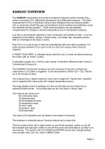
KANE457 OVERVIEW The KANE457 Combustion and Ambient Analyser measures carbon dioxide (CO2), carbon monoxide (CO), differential temperature and differential pressure. The direct measurement of CO2 is achieved using a Kane designed infra-red sensing system. CO2 is measured at both flue gas concentrations and at ambient concentrations using two separate sensing systems. These sensing systems are automatically compensated for changes in ambient temperature and in atmospheric pressure. Low flow is automatically detected in both combustion and ambient modes. It can be triggered by low battery voltage,...
Open the catalog to page 4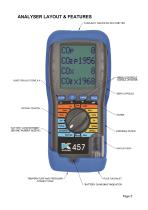
ANALYSER LAYOUT & FEATURES TASKLIGHT AND INFRA-RED EMITTER ROTARY SWITCH BATTERY COMPARTMENT (BEHIND RUBBER SLEEVE) ■MENU CONTROLS SCROLL UP'DOWN ZERO CAPSULE PARTICLE FILTER WATER TRAP "BATTERY CHARGING" INDICATOR
Open the catalog to page 5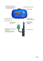
Temperature Connections * Flue Probe Temperature (T1 Pressure Connections Flue Probe Temperature Plug be on the right hand side. Battery Charger Connection Walertrap Drain With Red Screw Plug lack Connector (Plugs Into Flue Flue Probe Hose
Open the catalog to page 6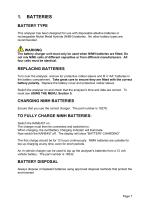
BATTERY TYPE This analyser has been designed for use with disposable alkaline batteries or rechargeable Nickel Metal Hydride (NiMH) batteries. No other battery types are recommended. WARNING The battery charger unit must only be used when NiMH batteries are fitted. Do not mix NiMh cells of different capacities or from different manufacturers. All four cells must be identical. REPLACING BATTERIES Turn over the analyser, remove its’ protective rubber sleeve and fit 4 “AA” batteries in the battery compartment. Take great care to ensure they are fitted with the correct battery polarity. Replace the...
Open the catalog to page 7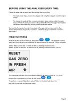
BEFORE USING THE ANALYSER EVERY TIME: Check the water trap is empty and the particle filter is not dirty: - To empty water trap, unscrew its stopper and re-tighten stopper once the trap is empty. To change the particle filter, remove protective rubber sleeve, slide the water trap unit from the analyser, remove the particle filter from its’ spigot and replace. Reconnect the water trap unit and rubber protective sleeve. Connect the flue probe hose to the analyser’s flue gas inlet and connect the flue probe’s temperature plug to the T1 socket – check the plug’s orientation is correct see Page 6....
Open the catalog to page 8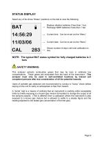
STATUS DISPLAY Select any of the three “Status” positions on the dial to view the following: Replace alkaline batteries if less than 1 bar. → Recharge NiMH batteries if less than 1 bar. → Current time. Can be re-set via the “Menu”. → Current date. Can be re-set via the “Menu”. Shows number of days until next calibration is NOTE: The typical BAT status symbol for fully charged batteries is 3 bars SAFETY WARNING This analyser extracts combustion gases that may be toxic in relatively low concentrations. These gases are exhausted from the back of the instrument. This analyser must only be used in...
Open the catalog to page 9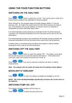
USING THE FOUR FUNCTION BUTTONS: SWITCHING ON THE ANALYSER: Press / button to switch the unit ON. This must be done in fresh air to ensure that the analyser auto calibrates its’ sensors properly. When switched on, the analyser beeps and briefly displays battery %, fuel and pressure units. Its’ bottom line counts down from 90 until the sensors are ready to use. If the analyser will not auto calibrate, its’ sensors need to be replaced or recalibrated by a Kane authorised repair centre. If an inlet temperature probe (optional) is connected into the T2 socket during its’ countdown, the measured temperature...
Open the catalog to page 10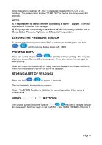
When the pump is switched off “-PO-" is displayed instead of the O2, CO & CO2 readings. The analyser also displays "PUMP OFF" on the top line approx every 40 seconds. NOTES: 1) The pump will not switch off if the CO reading is above to protect the CO sensor from damage. 2) The pump will automatically switch itself off when the rotary switch is set to Menu, Status, Pressure, Tightness or Differential Temperature. ZEROING THE PRESSURE SENSOR To re-zero the pressure sensor when “Prs” is selected on the dial, press and hold / until the top line display shows CAL ZERO. PRINTING DATA Press and quickly...
Open the catalog to page 11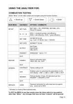
USING THE ANALYSER FOR: COMBUSTION TESTING Select “Menu” on the rotary switch and navigate using the function buttons: MAIN MENU OPTIONS / COMMENTS NAT GAS, L OIL, PROPANE, BUTANE, LPG, PELLETS (wood) Ef(C) = condensing boiler nett efficiency Ef(N) = nett efficiency, Ef(G) = gross efficiency DD/MM/YY format Std Printer Fast Printer XML DATA EXIT REPORT Stored combustion tests: VIEW, DEL ALL, EXIT EXIT CONTRAST Enables users to customise the parameters on the AUX display: LINE 1, LINE 2, LINE 3, LINE 4, EXIT Printout header, 2 lines, 20 characters per line: HEADER 1, HEADER 2, EXIT EXIT SERVICE...
Open the catalog to page 12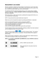
MEASURING FLUE GASES After the countdown is finished and the analyser is correctly set up, put its’ flue probe into the appliance’s sampling point. The tip of the probe should be at the centre of the flue. Use the flue probe’s depth stop cone to set the position. For appliances that have internal sampling points you can connect using a suitable plastic or rubber hose. Always remember to refit the covers/seals once sampling has been completed. With balanced flues, make sure the probe is positioned far enough into the flue so no air can ‘back flush’ into the probe. NOTE: Ensure that the flue probe...
Open the catalog to page 13All Kane International catalogs and technical brochures
 Essential instruments 2018
32 Pages
 Automotive Essential instruments
20 Pages
 Essential instruments 2017
44 Pages
 KANE425
36 Pages
 KANE450
36 Pages
 KANE455
52 Pages
 KANE251/KANE255
2 Pages
 KANE451plus
52 Pages
 KANE251 & KANE255
2 Pages
 Infra-red Thermometer INF151
2 Pages
 Pocket Thermometer PDT550
2 Pages
 KM9106 Quintox
4 Pages
 Combustion Analyser KANE940
2 Pages
 AUTO5-4
3 Pages
 AUTO5-3
3 Pages
 AUTO5-1
4 Pages
 KANE77
2 Pages
 CO-SENSE
1 Page
 KANE ALERT CO2
2 Pages
 DL49 Digital Clamp-on Multimeter
2 Pages
 INF151 Infra-red thermometer
4 Pages
 KANE250 Combustion Meter
2 Pages
 gas leak detection
4 Pages


- AMOT digital camera
- AMOT temperature sensor
- Gas analyzer
- Concentration analyzer
- AMOT infrared camera
- Pressure gauge
- AMOT digital thermometer
- AMOT portable tester
- AMOT portable analyzer
- AMOT digital tester
- Thermocouple temperature transducer
- Thermographic camera
- Oxygen analyzer
- AMOT industrial tester
- IR pyrometer
- Compact analyzer
- Leak monitor
- AMOT voltage tester
- Infrared analyser
- Gas pressure gauge