 Website:
KALEJA GmbH
Catalog excerpts
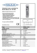
Industrial motor controller for BLDC-Motors 24 / 48 VDC Design for output currents up to 12 A Control with following functions: - speed control by analog input - additional adjustable speed input - reversal of direction of rotation - selectable dynamic braking - adjustable acceleration and deceleration ramp - current limitation or current shut off selectable - short circuit detection To snap onto DIN rail EN 50022 Operating data:_ Nominal voltage_ Supply voltage_ 2 digital outputs, galvanic isolated_ 3 Hall sensor inputs for open-collector sensors Tecnical data: load circuit Max. current / continuous load current Short circuit current detection typ. Shut down time after short circuit typ. Power stage driver_ Other data_ Stop ramp (stop-ramp) TR4 Current monitoring delay (CM-delay)_TR3 Current adjustable with DIP-switch_ Dynamic brake (armature short circuit)_ Temperature monitoring / overvoltage protection Status indication : ready / error_ 15.07.2020 KL - Errors and technical modification subject to change. All rights reserved. © KALEJA GmbH. KALEJA GmbH Strubelweg 14 D-73553 Alfdorf Tel.:+49 7172 93711 0 info@kaleia.com
Open the catalog to page 1
Housing, terminals, printed circuit board _UL94V-0 The module M5-BL-12-48 is operational after the stated initializing delay elapsed. The module M5-BL-12-48 is a motor control for brushless DC-motors, intended for the usage in an industrial environment. It ensures reliable switching on and off and controlled operation of BLDC motors. The module is provided with: - digital inputs for CW and CCW direction - digital input to switch between 2 independent adjustable target speeds - digital input for activation of dynamic braking - digital input to switch between current limitation or current...
Open the catalog to page 2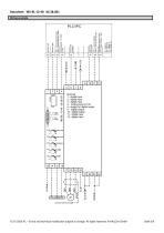
Datasheet M5-BL-12-48 06.38.001 Wiring example 15.07.2020 KL – Errors and technical modification subject to change. All rights reserved. © KALEJA GmbH
Open the catalog to page 3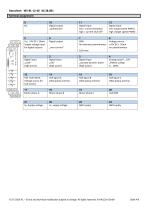
15.07.2020 KL - Errors and technical modification subject to change. All rights reserved. © KALEJA GmbH
Open the catalog to page 4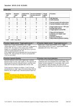
Digital input „Target speed PWM2“ (12) is „high“ Target speed source 2 is active. Target speed PWM2 adjustable with trimer TR2 is used. Dynamic braking is active when digital input „activate dynamic brake" (3) has „high“ signal. A „low“ signal at (3), deactivates the dynamic braking function, and the motor stops with the stop ramp adjusted with trimmer TR4. If both inputs for direction of rotation (1 and 2) are set simultaneously to „high“ signal, the device stops with the behavior set on digital input “activate dynamic brake”(3). Attention! Short-circuit braking is only allowed for motors...
Open the catalog to page 5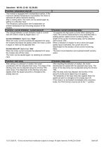
| Function: temperature shut-off | The change between current limitation mode or current shut-off mode is made by digital input (11): Current limitation: digital input “high“ When the motor current exceeds the adjusted limit value, the module decreases the speed unless the motor current is equal or lower as the adjusted limit. Current shut-off: digital input “low“ When the motor current exceeds the adjusted limit value, the module shut-off the motor. The motor can be started again, by resetting of a direction The module is equipped with a temperature sensor. If the maximum allowed...
Open the catalog to page 6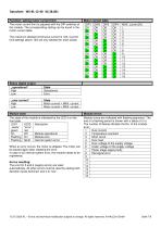
Function: setting motor current limit 15.07.2020 KL - Errors and technical modification subject to change. All rights reserved. © KALEJA GmbH
Open the catalog to page 7
15.07.2020 KL - Errors and technical modification subject to change. All rights reserved. © KALEJA GmbH
Open the catalog to page 8
Maximum operational data The maximum operating data must not be exceeded. Installation The installation and start-up must be performed by specialist personnel exclusively. All affected components must be disconnected from the mains. Start-up For the first start-up, the motor should be operated without load. Risk of death Do not touch live parts after switching on! The assembly must be operated exclusively on safety extra-low voltage. With operation under extra-low voltage (e.g. via autotransformer), death or injury can occur. Fire protection The assembly must be installed in a switch...
Open the catalog to page 9All KALEJA GmbH catalogs and technical brochures
-
M5-2QB-12-48 06.38.007
9 Pages
-
M-MWS-6-30
1 Pages
-
M-MRI-3-30
2 Pages
-
M-BL-5-30
2 Pages
-
M-MZ-4-30
2 Pages
-
Maxi-1Q-4-30
2 Pages
-
M-1Q-6-30
2 Pages
-
M-4Q-6-30
2 Pages
-
M-2Q-6-30
2 Pages
-
MAXI-GMF-8-30
4 Pages
-
M-S-6-30
2 Pages
-
Maxi-S-4-30
2 Pages
-
MAXI-MW-8-30
4 Pages
-
M2-CMR-5-30 06.34.018
6 Pages
-
Mini-SO-50-30
1 Pages
-
Mini-OM-50-30
1 Pages
-
Mini-OM-08-30
1 Pages
-
M2-MR-5-30
6 Pages
-
02.01.115_Mini-OM-25-30
1 Pages
-
06.04.202
4 Pages
-
06.04.201_Maxi-M-8-30
4 Pages
-
M2-3DR-5-30
8 Pages
-
M2-MWS-6-30
7 Pages
-
M2-MWI-6-30
7 Pages
-
M3-2QB-5-12
7 Pages
-
M3-4Q-5-30
7 Pages
-
Maxi-IMD-5-60
3 Pages
-
Maxi-IM-5-60
3 Pages
-
MB-12
1 Pages
-
Midi-OM-100-30
1 Pages
-
USV-S-9-B
1 Pages
-
USV-S-25-S
1 Pages
-
M3-2QB-5-30
7 Pages
-
M2-MWT-6-30
7 Pages
-
06.34.008
2 Pages
-
06.04.032
2 Pages
-
06.34.006
7 Pages
-
06.34.002
6 Pages
-
01.01.212
1 Pages
-
01.01.213
1 Pages
-
02.01.104
1 Pages
-
02.01.116
1 Pages
-
02.01.117
1 Pages
-
02.01.130
1 Pages
-
02.03.226
1 Pages
-
02.06.201
1 Pages
-
04.08.001
1 Pages
-
06.04.007
2 Pages
-
06.04.008
2 Pages
-
06.04.012
1 Pages
-
06.04.014
1 Pages
-
06.04.016
2 Pages
-
06.04.019
2 Pages
-
06.04.021
2 Pages
-
06.04.025
2 Pages
-
06.04.031
2 Pages
-
06.04.039
2 Pages
-
06.04.046
2 Pages
-
06.04.048
2 Pages
-
06.04.049
2 Pages
-
06.04.051
2 Pages
-
06.04.054
2 Pages
-
06.04.056
2 Pages
-
06.04.059
2 Pages
-
06.04.066
2 Pages
-
06.04.075
2 Pages
-
06.04.078
1 Pages
-
06.04.083
2 Pages
-
06.04.085
2 Pages
-
06.04.093
2 Pages
-
06.34.001
5 Pages
-
01.01.012
1 Pages
-
01.01.011E
1 Pages
-
01.01.007
1 Pages


