
- Catalogs
- KALEJA GmbH
- M5-2QB-12-48 06.38.007


M5-2QB-12-48 06.38.007

M5-2QB-12-48 06.38.007
Overview
The M5-2QB-12-48 is an industrial DC motor controller designed for 24/48 VDC motors with switching currents up to 12 A. It is intended for reliable motor control in industrial environments and mounts on a DIN rail (EN 50022) with a compact width of 22.5 mm.
Key Features and Functions
- Speed control via analog input (0–10 V, 24 V tolerant)
- Adjustable creep speed
- Direction reversal (left/right)
- Switchable dynamic braking (armature short circuit)
- Adjustable start and stop ramps
- Current limiting and current shutdown selectable
- Short circuit detection with fast shutdown (~100 µs)
- Temperature monitoring and overvoltage protection
- Status indication via green (ready) and red (error) LEDs
Technical Specifications
Electrical Data
- Nominal voltage: 24 / 48 VDC
- Supply voltage range: 15 to 58 VDC
- Max continuous current: 12 A (typical max 24 A)
- Short circuit detection current: 150 A
- Power driver: MOS-FET
- Digital inputs: 5 inputs at 24 VDC
- Analog input: 0–10 V, 24 V tolerant, input impedance ~98.5 kΩ
- Digital outputs: 2 galvanically isolated outputs, 24 VDC, 50 mA max, short-circuit proof
Mechanical and Environmental Data
- Dimensions: 114.5 x 22.5 x 99 mm
- Weight: 110 g
- Terminal type: Screw terminals, wire cross-section 0.2 to 2.5 mm²
- Mounting: Any orientation on DIN rail EN 50022
- Operating temperature: -20 to +60 °C
- Storage temperature: -30 to +85 °C
- Humidity: Up to 95%, non-condensing
- EMC compliance: EN 61000-6-2, EN 61800-3, EN 61000-6-4
- Flammability rating: UL94V-0 for housing, terminals, PCB
Control Inputs and Outputs
- Digital inputs for left/right rotation, dynamic brake activation, current limit/shutdown selection, and speed setpoint selection
- Analog input for speed control scaling (0–10 V)
- Digital outputs indicate operational readiness and overcurrent status
Operating Modes and Functions
Speed Control
Two independent speed setpoints selectable via digital input. Each setpoint is adjustable by trim potentiometers (TR1 and TR2) controlling PWM duty cycle (5–97%). The analog input scales the PWM output from 0 to the selected setpoint maximum.
Dynamic Braking
Activated by a dedicated digital input. When enabled, the motor is braked by short-circuiting the armature. If both direction inputs are high simultaneously, the motor stops as if dynamic braking was activated.
Current Limiting and Shutdown
Selectable via digital input:
- Current Limiting (input high): If motor current exceeds the set maximum, speed is reduced to keep current within limits.
- Current Shutdown (input low): If current exceeds the limit, the motor is switched off. Restart requires resetting direction inputs.
A current monitoring delay (adjustable via TR3, 0–1000 ms) prevents false triggering during motor start or speed changes.
Start and Stop Ramps
- Start ramp (TR5): Adjustable acceleration time from 50 to 4000 ms.
- Stop ramp (TR4): Adjustable deceleration time from 0 to 4000 ms.
- Stop ramp also applies to speed changes via analog input.
- Setting TR4 fully negative enables immediate dynamic braking on stop.
Short Circuit and Temperature Protection
- Short circuit detection triggers shutdown within ~100 µs and locks the module for a fixed time.
- Temperature sensor shuts down motor if maximum temperature is exceeded; restart possible after cooldown.
Configuration and Settings
- Maximum motor current set via DIP switches (1 to 16 A). Settings above 12 A are for short-term use only.
- Trim potentiometers for speed setpoints, current monitoring delay, start and stop ramps.
Status Indication and Error Handling
- Green LED1 indicates ready state.
- Red LED2 indicates error state with blink codes for specific faults:
- 1: Overcurrent
- 2: Temperature error
- 3: Short circuit
- 4: Overload
- 5: Overvoltage supply
- 6: Undervoltage supply
- 7: Power stage error
- Errors stop the motor; reset by cycling direction inputs or module reset.
- Internal system errors require manual reset.
Installation and Safety Instructions
- Installation and commissioning must be performed by qualified personnel with power off.
- Initial operation should be without load.
- Do not touch live parts after power-on; module operates only on safety extra-low voltage.
- Module must be mounted in a suitable enclosure with appropriate fusing.
- Use EMC-compliant wiring; shielded cables and filters recommended if needed.
- Use approved power supplies and ensure all connected devices are industrial-grade.
- Unauthorized opening voids warranty and may cause hazards.
- Regular maintenance includes checking ventilation and cleaning cooling openings.
Additional Notes
- Empirical derating curve provided for operation at high continuous currents; ensure adequate wiring, spacing (minimum 20 mm between modules), and airflow.
- Module dimensions: 114.5 mm length, 22.5 mm width, 99 mm height.
Contact Information
KALEJA GmbH
Strübelweg 14, D-73553 Alfdorf, Germany
Phone: +49 7172 93711 0
Email: [email protected]
Website: www.kaleja.com
Catalog excerpts

Industrielle Motoransteuerung für DC-Motoren 24 / 48 VDC Ausführung für Schaltströme bis 12 A Steuerung mit folgenden Funktionen: - Drehzahlsteuerung Analogeingang - Schleichgang einstellbar - Drehrichtungsumkehr - Dynamische Bremsung zuschaltbar - Startrampe / Stopprampe einstellbar - Strombegrenzung / Stromabschaltung - Kurzschlusserkennung Zum Aufschnappen auf die DIN-Schiene EN 50022 Bezeichnung Artikelnummer Betriebsdaten: Nennspannung Versorgungsspannung 5 Digitaleingänge 1 Analogeingang 2 Digitalausgänge, galvanisch getrennt Technische Daten: Lastkreis Max. Strom / Dauerlaststrom typ. Kurzschlusserkennung typ. Abschaltzeit nach Kurzschluss typ. Leistungstreiber Sonstige Daten Startrampe (start-ramp) TR5 Stopprampe (stop-ramp) TR4 Ausblendzeit (CM-delay) TR3 PWM speed2 (PWM2) TR2 PWM speed2 (PWM1) TR1 Strom über DIP-Schalter einstellbar Dynamische Bremsung (Ankerkurzschluss) Temperaturüberwachung / Überspannungsschutz Statusanzeige: ready / errpr 20.07.2020 KL - Irrtümer und technische Änderungen vorbehalten. Alle Rechte vorbehalten. KALEJA GmbH Strübelweg 14 D-73553 Alfdorf Tel.:+49 7172 93711 0 in
Open the catalog to page 1
Gehause, Klemmen, Leiterplatte _UL94V-0 Das Modul ist nach Ablauf der angegebenen Startzeit betriebsbereit. Die Startzeit beginnt ab Anlegen der Versorgungsspannung. Das Modul M5-2QB-12-48 ist eine Motorsteuerung fur DC-Motoren, zur Verwendung im industriellen Umfeld. Sie gewahrleistet das zuverlassige Ein- und Ausschalten von Motoren. Das Modul verfugt uber: - Digitaleingange fur Rechts- und Linkslauf - Digitaleingang fur 2 unabhangig einstellbare Drehzahlen - Digitaleingang zur Aktivierung der dynamischen Bremse - Digitaleingang zur Umschaltung von Strombegrenzung oder Uberstromabschaltung...
Open the catalog to page 2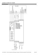
Datenblatt M5-2QB-12-48 06.38.007 Beschaltung Beispiel 20.07.2020 KL - Irrtümer und technische Änderungen vorbehalten. Alle Rechte vorbehalten. © KALEJA GmbH
Open the catalog to page 3
20.07.2020 KL - Irrtumer und technische Anderungen vorbehalten. Alle Rechte vorbehalten. © KALEJA GmbH
Open the catalog to page 4
Digitaleingang „Sollwert PWM2“ (12) „low“ Sollwertquelle 1 ist aktiv. PWM max. wird uber Trimmer TR1 eingestellt. Die PWM kann uber den Analogeingang „PWM1 Skalierung“ (4) von 0 bis zu der an TR1 eingestellten PWM max. verandert werden. Soll das Modul nur mit der intern eingestellten Drehzahl, TR1, betrieben werden, muss die Klemme (4) auf +10V |_Funkt^^:<Dreh^ih^teueirun^SoJJ^ertqueMe<2^_^^_LFunkt^n_DrehzahJsteu^run£^oJJ^ertq^jJtei2^_^_ Digitaleingang „Sollwert PWM2“ (12) „high“ Sollwertquelle 2 ist aktiv. Der Sollwert von Trimmer TR2 (PWM2) wird verwendet. Die dynamische Bremse ist aktiv wenn...
Open the catalog to page 5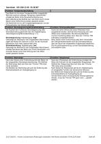
Nach dem Setzen einer Drehrichtung wird der Motor mit der eingestellten Startrampe beschleunigt. Die Steilheit der Startrampe lasst sich uber den Trimmer TR5 (start-ramp) einstellen. Die Steilheit der Startrampe gilt auch bei Anderung des Drehzahlsollwerts am Analogeingang (4). Nach dem Rucksetzen der Drehrichtung verzogert der Motor die Drehzahl mit der eingestellten Stopprampe. Die Steilheit der Stopprampe lasst sich uber den T rimmer TR4 (stop-ramp) einstellen. Nach Ablauf der Stopprampe gilt die am Digitaleingang (3) eingestellte Funktion der dynamischen Bremse. Die Steilheit der Stopprampe...
Open the catalog to page 6
20.07.2020 KL - Irrtumer und technische Anderungen vorbehalten. Alle Rechte vorbehalten. © KALEJA GmbH
Open the catalog to page 7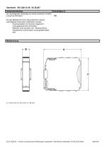
Datenblatt M5-2QB-12-48 06.38.007 Temperaturderating Die nachfolgende Deratingkurve wurde empirisch ermittelt und gilt als Richtwert. Für den Betrieb bei hohen Dauerströmen müssen nachfolgende Parameter eingehalten werden: Anschlusskabel mit maximal möglichem Leitungsquerschnitt verwenden. Modulen nicht anreihen min. Abstand 20mm Ausreichend Luftzirkulation muss gewährleistet sein. 20.07.2020 KL - Irrtümer und technische Änderungen vorbehalten. Alle Rechte vorbehalten. © KALEJA GmbH
Open the catalog to page 8
Datenblatt M5-2QB-12-48 06.38.007 Sicherheitshinweise Max. Betriebsdaten Die maximalen Betriebsdaten dürfen nicht überschritten werden. Installation Die Installation und Inbetriebnahme darf nur von Fachpersonal vorgenommen werden. Alle betroffenen Komponenten müssen stromlos sein. Inbetriebnahme Für die Erstinbetriebnahme soll der Motor ohne Last betrieben werden. Lebensgefahr Nach dem Einschalten keine spannungsführenden Teile berühren! Das Modul darf nur an Schutzkleinspannung betrieben werden! Bei Betrieb an Kleinspannung (z.B. über Spartrafo) kann Verletzung oder Tod eintreten! Brandschutz...
Open the catalog to page 9All KALEJA GmbH catalogs and technical brochures
 M5-BL-12-48 06.38.001
9 Pages
 M-MWS-6-30
1 Page
 M-MRI-3-30
2 Pages
 M-BL-5-30
2 Pages
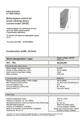 M-MZ-4-30
2 Pages
 Maxi-1Q-4-30
2 Pages
 M-1Q-6-30
2 Pages
 M-4Q-6-30
2 Pages
 M-2Q-6-30
2 Pages
 MAXI-GMF-8-30
4 Pages
 M-S-6-30
2 Pages
 Maxi-S-4-30
2 Pages
 MAXI-MW-8-30
4 Pages
 M2-CMR-5-30 06.34.018
6 Pages
 Mini-SO-50-30
1 Page
 Mini-OM-50-30
1 Page
 Mini-OM-08-30
1 Page
 M2-MR-5-30
6 Pages
 02.01.115_Mini-OM-25-30
1 Page
 06.04.202
4 Pages
 06.04.201_Maxi-M-8-30
4 Pages
 M3-4Q-5-30
7 Pages
 M3-2QB-5-12
7 Pages
 M2-MWI-6-30
7 Pages
 M2-MWS-6-30
7 Pages
 M2-3DR-5-30
8 Pages
 Maxi-IMD-5-60
3 Pages
 Maxi-IM-5-60
3 Pages
 MB-12
MB-121 Page
 Midi-OM-100-30
1 Page
 USV-S-9-B
1 Page
 USV-S-25-S
1 Page
 06.04.032
2 Pages
 M3-2QB-5-30
7 Pages
 M2-MWT-6-30
7 Pages
 06.34.008
2 Pages
 06.34.006
7 Pages
 06.34.002
6 Pages
 01.01.212
1 Page
 01.01.213
1 Page
 02.01.104
1 Page
 02.01.116
1 Page
 02.01.117
1 Page
 02.01.130
1 Page
 02.03.226
1 Page
 02.06.201
1 Page
 04.08.001
1 Page
 06.04.007
2 Pages
 06.04.008
2 Pages
 06.04.012
1 Page
 06.04.014
1 Page
 06.04.016
2 Pages
 06.04.019
2 Pages
 06.04.021
2 Pages
 06.04.025
2 Pages
 06.04.031
2 Pages
 06.04.039
2 Pages
 06.04.046
2 Pages
 06.04.048
2 Pages
 06.04.049
2 Pages
 06.04.051
2 Pages
 06.04.054
2 Pages
 06.04.056
2 Pages
 06.04.059
2 Pages
 06.04.066
2 Pages
 06.04.075
2 Pages
 06.04.078
1 Page
 06.04.083
2 Pages
 06.04.085
2 Pages
 06.04.093
2 Pages
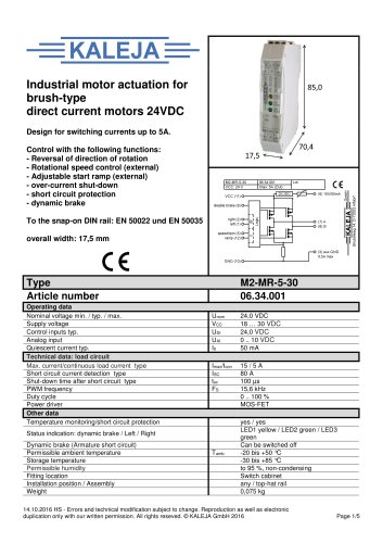 06.34.001
5 Pages
 01.01.012
1 Page
 01.01.011E
1 Page
 01.01.007
1 Page
- Switching relay
- DC motor controller
- Solid state relay
- Speed controller
- Choke coil
- Brushless motor control
- DC solid state relay
- Digital input motor controller
- Motor controller with speed control
- Compact motor controller
- Digital output motor controller
- Analog input motor controller
- DC speed controller
- Current choke
- Brushed motor controller
- Analog motor controller
- Open-loop motor controller
- DIN rail solid state relay
- Torque control motor controller