
- Catalogs
- KALEJA GmbH
- M3-2QB-5-30


M3-2QB-5-30

M3-2QB-5-30
Catalog excerpts
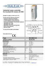
Industrial motor controller for brushed DC motors 24 VDC Design for output currents up to 5 A Control with the following functions: - reversal of direction of rotation - rotational speed control (external) - current limitation control (external) - overcurrent limitation / Overcurrent shutdown - adjustable start ramp - adjustable stop ramp - adjustable current monitoring delay - short circuit detection - dynamic brake To snap onto the DIN rail EN 50022 Article number 27.11.2018 KL - Errors and technical modification subject to change. All rights reserved. KALEJA GmbH Strubelweg 14 D-73553 Alfdorf, Germany Phone: +49 7172 93711 0 [email protected]
Open the catalog to page 1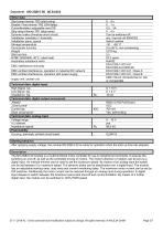
Housing, terminals, printed circuit board _UL94V-0 After applying supply voltage, the module M3-2QB-5-30 is ready for operation when the start up time has elapsed. The M3-2QB-5-30 module is a multi-functional motor controller for use in industrial environments. It ensures the switching on and off, as well as the controlled driving of motors. The motor's direction of rotation can be set via a digital input. An internal trimmer can be used to set the maximum speed. By means of an analog input the speed can be set between 0 to maximum speed. The dynamic brake can be deactivated over a digital...
Open the catalog to page 2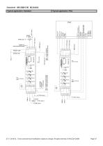
Datasheet M3-2QB-5-30 06.34.010 Typical application: Standard 27.11.2018 KL - Errors and technical modification subject to change. All rights reserved. © KALEJA GmbH
Open the catalog to page 3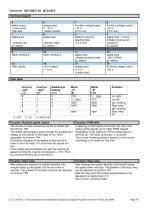
The maximum output speed can be set or limited with the trimmer TR4. The speed setting itself is given through the analog input voltage at terminal (6) in the range of 0 to 100% adjustable via trimmer TR4. An analog voltage must be applied at terminal (6) in order to turn the motor. 0 V at terminal (6) equals to 0 rpm. If the module should operate only with the internal set speed, terminal (6) must be connected to + 10V / VCC, e.g. connect terminal (6) to terminal (7). After setting any direction of rotation direction, the module ramps up the speed until the set value is reached. The gradient...
Open the catalog to page 4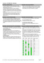
27.11.2018 KL - Errors and technical modification subject to change. All rights reserved. © KALEJA GmbH
Open the catalog to page 5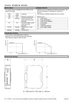
Display elements The module status is displayed via the LEDs on the module front plate. Module errors are displayed as flashing sequences. The end of the sequence is indicated by a pause of 1 second. The number of flashes indicates the error number. | Temperature derating ~ If the module is assembled with a minimum clearance of 10 mm on both sides these derating The curves are valid for 100% on-time 27.11.2018 KL - Errors and technical modification subject to change. All rights reserved. © KALEJA GmbH
Open the catalog to page 6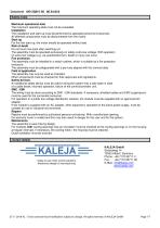
Maximum operational data The maximum operating data must not be exceeded. Installation The installation and start-up must be performed by specialist personnel exclusively. All affected components must be disconnected from the mains. Start-up For the first start-up, the motor should be operated without load. Risk of death Do not touch live parts after switching on! The assembly must be operated exclusively on safety extra-low voltage. With operation on extra-low voltage (e.g. via autotransformer), death or injury can occur. Fire protection The assembly must be installed in a switch cabinet, which...
Open the catalog to page 7All KALEJA GmbH catalogs and technical brochures
 M5-2QB-12-48 06.38.007
9 Pages
 M5-BL-12-48 06.38.001
9 Pages
 M-MWS-6-30
1 Page
 M-MRI-3-30
2 Pages
 M-BL-5-30
2 Pages
 M-MZ-4-30
2 Pages
 Maxi-1Q-4-30
2 Pages
 M-1Q-6-30
2 Pages
 M-4Q-6-30
2 Pages
 M-2Q-6-30
2 Pages
 MAXI-GMF-8-30
4 Pages
 M-S-6-30
2 Pages
 Maxi-S-4-30
2 Pages
 MAXI-MW-8-30
4 Pages
 M2-CMR-5-30 06.34.018
6 Pages
 Mini-SO-50-30
1 Page
 Mini-OM-50-30
1 Page
 Mini-OM-08-30
1 Page
 M2-MR-5-30
6 Pages
 02.01.115_Mini-OM-25-30
1 Page
 06.04.202
4 Pages
 06.04.201_Maxi-M-8-30
4 Pages
 M3-4Q-5-30
7 Pages
 M3-2QB-5-12
7 Pages
 M2-MWI-6-30
7 Pages
 M2-MWS-6-30
7 Pages
 M2-3DR-5-30
8 Pages
 Maxi-IMD-5-60
3 Pages
 Maxi-IM-5-60
3 Pages
 MB-12
MB-121 Page
 Midi-OM-100-30
1 Page
 USV-S-9-B
1 Page
 USV-S-25-S
1 Page
 06.04.032
2 Pages
 M2-MWT-6-30
7 Pages
 06.34.008
2 Pages
 06.34.006
7 Pages
 06.34.002
6 Pages
 01.01.212
1 Page
 01.01.213
1 Page
 02.01.104
1 Page
 02.01.116
1 Page
 02.01.117
1 Page
 02.01.130
1 Page
 02.03.226
1 Page
 02.06.201
1 Page
 04.08.001
1 Page
 06.04.007
2 Pages
 06.04.008
2 Pages
 06.04.012
1 Page
 06.04.014
1 Page
 06.04.016
2 Pages
 06.04.019
2 Pages
 06.04.021
2 Pages
 06.04.025
2 Pages
 06.04.031
2 Pages
 06.04.039
2 Pages
 06.04.046
2 Pages
 06.04.048
2 Pages
 06.04.049
2 Pages
 06.04.051
2 Pages
 06.04.054
2 Pages
 06.04.056
2 Pages
 06.04.059
2 Pages
 06.04.066
2 Pages
 06.04.075
2 Pages
 06.04.078
1 Page
 06.04.083
2 Pages
 06.04.085
2 Pages
 06.04.093
2 Pages
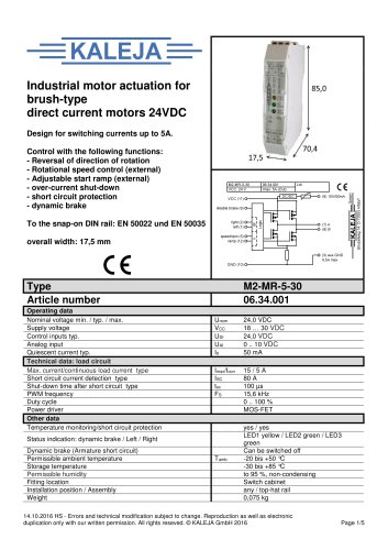 06.34.001
5 Pages
 01.01.012
1 Page
 01.01.011E
1 Page
 01.01.007
1 Page
- Switching relay
- DC motor controller
- Solid state relay
- Speed controller
- Choke coil
- Brushless motor control
- DC solid state relay
- Digital input motor controller
- Motor controller with speed control
- Compact motor controller
- Digital output motor controller
- Analog input motor controller
- DC speed controller
- Current choke
- Brushed motor controller
- Analog motor controller
- Open-loop motor controller
- DIN rail solid state relay
- Torque control motor controller