- Catalogs
- KALEJA GmbH
- M2-MWI-6-30
M2-MWI-6-30
1 /7Pages

M2-MWI-6-30
1 /7Pages
Catalog excerpts

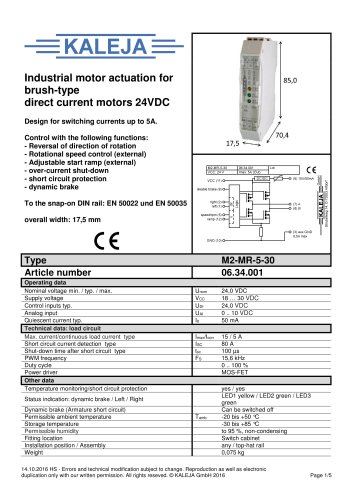
Design for output currents up to 6 A Control with the following functions: - reversal of direction of rotation - overcurrent shutdown - overcurrent indication output - adjustable current monitoring delay - short circuit detection - dynamic brake To snap onto the DIN rail EN 50022 Operating data 27.11.2018 KL - Errors and technical modification subject to change. All rights reserved. KALEJA GmbH Strubelweg 14 D-73553 Alfdorf, Germany Phone: +49 7172 93711 0 [email protected]
Open the catalog to page 1
Housing, terminals, printed circuit board _UL94V-0 After applying supply voltage, the module is ready for operation when the start up time has elapsed. The module is a two quadrant motor control for use in industrial environments. It ensures the switching on and off, as well as the controlled driving of motors. Over a DIP switch the motor current limit value for the overcurrent shutdown is adjustable. The continuous load current form the module is 6A. A digital output reports if the module is in overcurrent shutdown mode. Current monitoring delay is adjustable over Trimmer TR1. The module has...
Open the catalog to page 2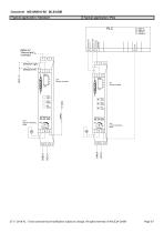
^Typical application: Standard digital out direction left ©error LED1 Co) r'ght \ZJ LED2 /T\ left W LED3 27.11.2018 KL - Errors and technical modification subject to change. All rights reserved. © KALEJA GmbH
Open the catalog to page 3
The module has a DIP switch to adjust the current limit. switch on the module. The maximum permissible motor current is set via the In case of an overcurrent shut-off the digital output (4) is set HIGH. To reset the module set a HIGH Signal on digital input “reset” (9) or set both direction inputs(1 & 2) to low and start again in any direction. overload shutdown: The module is internally protected with an overload shutdown. In case of rising of the motor current over the rated continuous load current the module switches of with a thermal safety function. After the shutdown the module is locked...
Open the catalog to page 4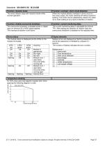
|_Temperaturederatingi^^^^^^^_^^^^^^^ At 100% duty cycle and aligned modules with 10mm spacing the following diagram is valid. 27.11.2018 KL - Errors and technical modification subject to change. All rights reserved. © KALEJA GmbH
Open the catalog to page 5
Datasheet M2-MWI-6-30 06.34.008 Dimensional drawing 27.11.2018 KL - Errors and technical modification subject to change. All rights reserved. © KALEJA GmbH
Open the catalog to page 6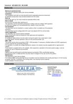
Maximum operational data The maximum operating data must not be exceeded. Installation The installation and start-up must be performed by specialist personnel exclusively. All affected components must be disconnected from the mains. Start-up For the first start-up, the motor should be operated without load. Risk of death Do not touch live parts after switching on! The assembly must be operated exclusively on safety extra-low voltage. With operation on extra-low voltage (e.g. via autotransformer), death or injury can occur. Fire protection The assembly must be installed in a switch cabinet, which...
Open the catalog to page 7All KALEJA GmbH catalogs and technical brochures
 M5-2QB-12-48 06.38.007
9 Pages
 M5-BL-12-48 06.38.001
9 Pages
 M-MWS-6-30
1 Page
 M-MRI-3-30
2 Pages
 M-BL-5-30
2 Pages
 M-MZ-4-30
2 Pages
 Maxi-1Q-4-30
2 Pages
 M-1Q-6-30
2 Pages
 M-4Q-6-30
2 Pages
 M-2Q-6-30
2 Pages
 MAXI-GMF-8-30
4 Pages
 M-S-6-30
2 Pages
 Maxi-S-4-30
2 Pages
 MAXI-MW-8-30
4 Pages
 M2-CMR-5-30 06.34.018
6 Pages
 Mini-SO-50-30
1 Page
 Mini-OM-50-30
1 Page
 Mini-OM-08-30
1 Page
 M2-MR-5-30
6 Pages
 02.01.115_Mini-OM-25-30
1 Page
 06.04.202
4 Pages
 06.04.201_Maxi-M-8-30
4 Pages
 M3-4Q-5-30
7 Pages
 M3-2QB-5-12
7 Pages
 M2-MWS-6-30
7 Pages
 M2-3DR-5-30
8 Pages
 Maxi-IMD-5-60
3 Pages
 Maxi-IM-5-60
3 Pages
 MB-12
MB-121 Page
 Midi-OM-100-30
1 Page
 USV-S-9-B
1 Page
 USV-S-25-S
1 Page
 06.04.032
2 Pages
 M3-2QB-5-30
7 Pages
 M2-MWT-6-30
7 Pages
 06.34.008
2 Pages
 06.34.006
7 Pages
 06.34.002
6 Pages
 01.01.212
1 Page
 01.01.213
1 Page
 02.01.104
1 Page
 02.01.116
1 Page
 02.01.117
1 Page
 02.01.130
1 Page
 02.03.226
1 Page
 02.06.201
1 Page
 04.08.001
1 Page
 06.04.007
2 Pages
 06.04.008
2 Pages
 06.04.012
1 Page
 06.04.014
1 Page
 06.04.016
2 Pages
 06.04.019
2 Pages
 06.04.021
2 Pages
 06.04.025
2 Pages
 06.04.031
2 Pages
 06.04.039
2 Pages
 06.04.046
2 Pages
 06.04.048
2 Pages
 06.04.049
2 Pages
 06.04.051
2 Pages
 06.04.054
2 Pages
 06.04.056
2 Pages
 06.04.059
2 Pages
 06.04.066
2 Pages
 06.04.075
2 Pages
 06.04.078
1 Page
 06.04.083
2 Pages
 06.04.085
2 Pages
 06.04.093
2 Pages
 06.34.001
5 Pages
 01.01.012
1 Page
 01.01.011E
1 Page
 01.01.007
1 Page
- Switching relay
- Motor controller
- DC motor controller
- Solid state relay
- Speed controller
- Choke coil
- Brushless motor control
- Digital input motor controller
- DC solid state relay
- Compact motor controller
- Motor controller with speed control
- Digital output motor controller
- Analog input motor controller
- DC speed controller
- Current choke
- Brushed motor controller
- Analog motor controller
- Open-loop motor controller
- DIN rail solid state relay
- Torque control motor controller