
- Catalogs
- KALEJA GmbH
- M-MRI-3-30


M-MRI-3-30

M-MRI-3-30
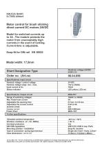
The document outlines the specifications for a motor control module designed for brush sticking direct current (DC) motors operating at 24VDC. It includes a snap-fit design for DIN rail EN 50022 and features a MOS-FET input circuit with a nominal voltage range of 19VDC to 35VDC. The input current at nominal voltage is 10mA, with status indicators provided by yellow and red LEDs.
The output circuit supports a range of switching voltages with a maximum rated load current of 3A. The module allows for adjustable opening time (0.5 to 2.0 seconds) and current control (0.4A to 4A). It includes dynamic braking and can handle an impulse current of 20A for 20 milliseconds.
The module operates within an allowable ambient temperature range of -20°C to +50°C and includes overload protection. It complies with DIN VDE regulations 0110 and 0160 in separate parts. The mounting position is modular with a snap-fit design, and the connection type is a spring-type terminal. The case dimensions are 17.5mm x 114.5mm x 99mm.
The module protects the motor from high currents during locking by switching off the motor after a set time under dynamic braking. A fixed time of approximately 300ms prevents current evaluation during motor acceleration. If excess current is detected during operation, the motor is switched off and remains blocked until a reset is triggered. The reset can be activated by a LOW signal at A1 and A2 or a HIGH signal at A3. The module includes a speed controller adjustable via a potentiometer or analog output SPS (0-10VDC).
The module is suitable for various applications, including protection for materials and tools, locking drive belts, conveyor belts, and trucks. It can substitute mechanical reversing relays by deactivating current monitoring, providing protection against excessive pressure and equipment damage.
Catalog excerpts
12.12.2017 AT - Errors and technical modification subject to change. Reproduction as well as electronic duplication only with our written permission. All rights reseved. © KALEJA GmbH 2015
Open the catalog to page 1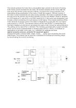
Clockwiese . . _ rotation A1 o Anticlockwise A2rotation Reset Measuring point
Open the catalog to page 2All KALEJA GmbH catalogs and technical brochures
 M5-2QB-12-48 06.38.007
9 Pages
 M5-BL-12-48 06.38.001
9 Pages
 M-MWS-6-30
1 Page
 M-BL-5-30
2 Pages
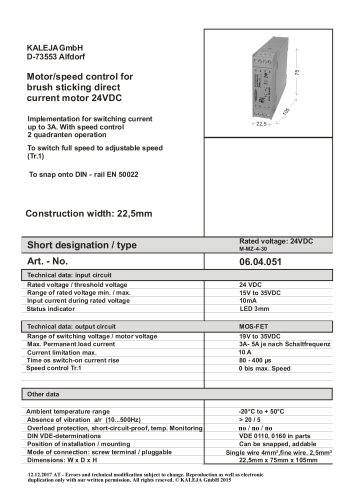 M-MZ-4-30
2 Pages
 Maxi-1Q-4-30
2 Pages
 M-1Q-6-30
2 Pages
 M-4Q-6-30
2 Pages
 M-2Q-6-30
2 Pages
 MAXI-GMF-8-30
4 Pages
 M-S-6-30
2 Pages
 Maxi-S-4-30
2 Pages
 MAXI-MW-8-30
4 Pages
 M2-CMR-5-30 06.34.018
6 Pages
 Mini-SO-50-30
1 Page
 Mini-OM-50-30
1 Page
 Mini-OM-08-30
1 Page
 M2-MR-5-30
6 Pages
 02.01.115_Mini-OM-25-30
1 Page
 06.04.202
4 Pages
 06.04.201_Maxi-M-8-30
4 Pages
 M3-4Q-5-30
7 Pages
 M3-2QB-5-12
7 Pages
 M2-MWI-6-30
7 Pages
 M2-MWS-6-30
7 Pages
 M2-3DR-5-30
8 Pages
 Maxi-IMD-5-60
3 Pages
 Maxi-IM-5-60
3 Pages
 MB-12
MB-121 Page
 Midi-OM-100-30
1 Page
 USV-S-9-B
1 Page
 USV-S-25-S
1 Page
 06.04.032
2 Pages
 M3-2QB-5-30
7 Pages
 M2-MWT-6-30
7 Pages
 06.34.008
2 Pages
 06.34.006
7 Pages
 06.34.002
6 Pages
 01.01.212
1 Page
 01.01.213
1 Page
 02.01.104
1 Page
 02.01.116
1 Page
 02.01.117
1 Page
 02.01.130
1 Page
 02.03.226
1 Page
 02.06.201
1 Page
 04.08.001
1 Page
 06.04.007
2 Pages
 06.04.008
2 Pages
 06.04.012
1 Page
 06.04.014
1 Page
 06.04.016
2 Pages
 06.04.019
2 Pages
 06.04.021
2 Pages
 06.04.025
2 Pages
 06.04.031
2 Pages
 06.04.039
2 Pages
 06.04.046
2 Pages
 06.04.048
2 Pages
 06.04.049
2 Pages
 06.04.051
2 Pages
 06.04.054
2 Pages
 06.04.056
2 Pages
 06.04.059
2 Pages
 06.04.066
2 Pages
 06.04.075
2 Pages
 06.04.078
1 Page
 06.04.083
2 Pages
 06.04.085
2 Pages
 06.04.093
2 Pages
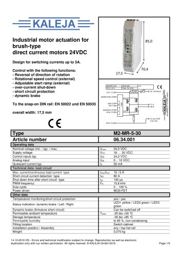 06.34.001
5 Pages
 01.01.012
1 Page
 01.01.011E
1 Page
 01.01.007
1 Page
- Switching relay
- Motor controller
- DC motor controller
- Solid state relay
- Choke coil
- Brushless motor control
- DC solid state relay
- Digital input motor controller
- Motor controller with speed control
- Compact motor controller
- Digital output motor controller
- Analog input motor controller
- DC speed controller
- Current choke
- Brushed motor controller
- Analog motor controller
- Open-loop motor controller
- DIN rail solid state relay
- Torque control motor controller