- Catalogs
- JWIPC TECHNOLOGY CO., LTD.
- AIoT7-H510 User’s Manual
AIoT7-H510 User’s Manual
1 /44Pages

AIoT7-H510 User’s Manual
1 /44Pages
Catalog excerpts
Disclaimer The content of this manual is the intellectual property of the Company, and the copyright belongs to the Company. The ownership of all parts of this product, including accessories and software, is vested in the Company. Without the written permission of the Company, this manual and its any content shall not be imitated, copied, extracted or translated into other languages in any form. We have carefully prepared this manual with an attitude of being responsible for users, but we do not guarantee that the contents of this manual are completely accurate. This manual is a purely technical...
Open the catalog to page 2
Chapter 1 General 1.1 Packing list Thank you for choosing our products. Please kindly confirm the integrity of the packaging of the motherboard you purchased. If there is any packaging damage or any shortage of accessories, please contact your dealer as soon as possible. ★ 1 * driver disc (industrial packaging: 1PCS/box) ★ 1 * SATA HDD adapter cable ★ 1 * special I/O buffer The specifications of the accompanying accessories above are provided for reference only, the actual specifications are subject to the actual product, and the Company reserves the right to modif
Open the catalog to page 5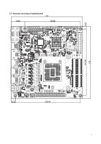
1.3 Structure drawing of motherboard
Open the catalog to page 7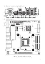
1.4 IO interface structure drawing of motherboard (This image is for reference only, please prevail in kind)
Open the catalog to page 8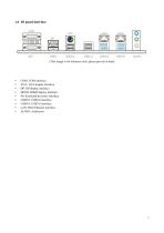
• HDMI: HDMI display interface • PS: Keyboard & mouse interface • USB2.0: USB2.0 interface • AUDIO: Audio port
Open the catalog to page 9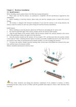
Chapter 2 Hardware installation 2.1 Install memory Before installing memory, please observe the following warning information: 1. Please make sure that the memory you purchased is compatible with the specifications supported by this motherboard. 2. Before installing or removing memory, please make sure that the computer power is turned off to prevent damage. 3. The memory is designed with fool-proof mechanism. If you insert the memory in the wrong direction, the memory cannot be inserted. In such case, please change the insertion direction immediately. Install memory: 1. Before installing or...
Open the catalog to page 10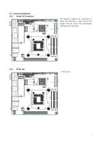
2.2 Connect peripherals 2.2.1 Serial ATA interface PCIE slot The interface supports the connection to Serial ATA hard disk or other devices that comply with the Serial ATA specification with Serial ATA flat cable.
Open the catalog to page 11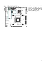
M.2 SATA slot, supports SSD; When installing this card, please insert the card at an angle of 30°, press down to the stud, and then fix it with screws.
Open the catalog to page 12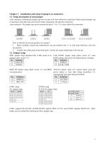
How to identify the first pin position of a jumper? 1. Please carefully examine the motherboard. Any pin marked with “1” or with white bold line is the first pin position. 2. Examine the solder pads on the back panel. Usually, the square-shaped pad is the first pin. 3.2 Jumper setup JME1 jumper setup (disabled ME, if ME needs to be CLR_COMS1 jumper setup (short circuit 2-3, clear updated, short circuit 1-2) BIOS settings, and restore the default factory settings) COM1 supports RS-232/485, JCOM2/JCOM3 supports PIN9 5V/12V, and JCOM3 supports RS232/TLL. Three modes can be switched by selecting...
Open the catalog to page 13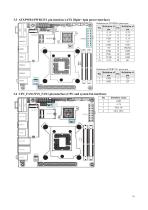
3.4 CPU_FAN1/SYS_FAN1 pin interface (CPU and system fan interface) Pin
Open the catalog to page 14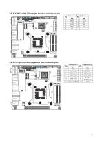
3.6 JESPI pin interface (expansion board interface pin) Pin
Open the catalog to page 15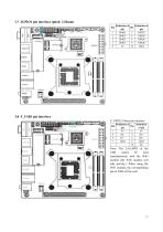
Note: The 2,4,6,8PIN of the USB cannot be used simultaneously with the WiFi module (the WiFi module will take priority). When using the WiFi module, the corresponding pin of USB will be null.
Open the catalog to page 16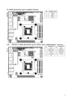
3.10 FPANEL1 2.54mm pin interface (power button / power / HDD indicator / reset key) Pin
Open the catalog to page 17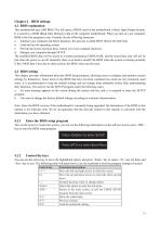
4.1 BIOS explanation This motherboard uses AMI BIOS. The full name of BIOS used by the motherboard is Basic Input Output System. It is stored in a ROM (Read-Only Memory) chip on the computer motherboard. When you turn on your computer, BIOS is the first program to run. It mainly has the following functions: a. Initialize your computer and detect hardware, this process is called POST (Power On Self Test). b. Load and run the operating system. c. Provide the lowest and most basic control over your computer hardware. d. Manage your computer through SETUP. The modified BIOS data will be stored in...
Open the catalog to page 18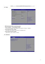
Save the modified CMOS settings and reboot • BIOS Information (BIOS related information) • System Language (system language setting) Set the system language of the computer in the format of <Chinese> <English>. • System Date(system date setting) Set the date of the computer in the format of “month/day/year”. • System Time(system time setting) Time format is <hour><minute><second>
Open the catalog to page 19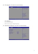
► CPU Configuration Press <Enter> key to enter the sub-menu CPU Configuration Set the central processing unit. Press <Esc> key to return to “Advanced” main menu ► Onboard Devices Configuration Press <Enter> key to enter the sub-menu
Open the catalog to page 20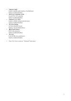
• Onboard Audio Enable or disable audio interface of motherboard. Options: Enabled,Disabled. • PCH LAN Controller (1219) Set the PCH LAN controller. Options: Enabled,Disabled. • Onboard LAN (1226) Enable or disable onboard network board. Options: Enabled.Disabled. • PS/2 Port Setting Set the keyboard & mouse. Options: Auto,KeyfQard,Mouse. • BIOS Write Protect BIOS write protection. Options: Enabled,Disabled. • Me Lock Lock the ME access permission. Options: Enabled,Disabled. • Press <Esc> key to return to “Advanced” main menu
Open the catalog to page 21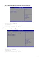
• Serial Port 1/2/3/4/5/6 Configuration Set the serial ports. Press <Esc> key to return to “Advanced” main menu Set Parareterf. of SerLaS Fnrl I (CDM^i NCTSI ldDSEC Super ID Conf Sjturat lan Super IO CniD ► Serial Port 2 ► Serial I'nr 1 3 ► Serial Fcrt A sc led Screen ■I. Select Item Enter: select +/-; ClWfge Opt. FIs Gar'«rdl Help FI's Previous Values Fe: Optimized Pefpujt* F10: SOW « Exit ESC: Exit • Serial Port 1/2/3/4 Configuration Set the serial ports. • Press <Esc> key to return to “Advanced” main menu
Open the catalog to page 22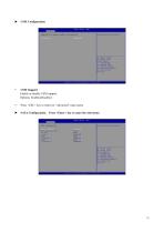
• CSM Support Enable or disable CSM support. Options: Enabled,Disabled. • Press <ESC> key to return to “Advanced” main menu ► SATA Configuration Press <Enter> key to enter the sub-menu
Open the catalog to page 23All JWIPC TECHNOLOGY CO., LTD. catalogs and technical brochures
 JWIPC Industrial Product Catalog
35 Pages
 ISG308
3 Pages
 ISG305
3 Pages
 ISG305P
3 Pages
 ISG308P
3 Pages
 ISF105
3 Pages
 ISF105P
3 Pages
 ISF108
3 Pages
 ISF108P
3 Pages
 ISG308P-24V
3 Pages
 ISG3200-10TS
4 Pages
 ISG3200-12TS-P
4 Pages
 ISG3200-28TS
4 Pages
 Datasheet JEA-E68I
3 Pages
Archived catalogs
 JEC-2510 (AMR-TGU) User’s Manual
40 Pages
 ISF106TF-P
2 Pages
 ISF108P-24V
2 Pages
 ISG3200-12TS
2 Pages
 ISG302TS-HPW
1 Page
 ISF102TF
1 Page
 ISF105TF-P
2 Pages
 S3200 Series-datasheet
2 Pages
 S4300 Series-datasheet
2 Pages
 S5600 Series-datasheet
2 Pages
 S5800 Series-datasheet
2 Pages
 S6200 Series-datasheet
2 Pages
 AIoT9-H510 User’s Manual
38 Pages
 JWIPC BOX PC Selection Guide
2 Pages
 Datasheet IPC-4U810
2 Pages
 E088 User’s Manual
19 Pages


- Panel PC
- Industrial panel PC
- Panel PC with touch screen
- Fanless panel PC
- Ethernet switch
- LCD panel PC
- LCD screen
- Monitor with touchscreen
- Industrial monitor
- Industrial computer
- HDMI monitor
- Intel® Core™ PC
- Fanless PC
- IP65 panel PC
- Intel® Core™ panel PC
- VESA mounting panel PC
- Industrial network switch
- HDMI PC
- Embedded PC
- Linux panel PC