


DRIVE SHAFTS for INDUSTRY

DRIVE SHAFTS for INDUSTRY
Drive shafts are critical components in the manufacturing industry, enabling the transfer of torque between non-aligned driving and driven shafts. They are essential for high power output and efficiency in applications such as rolling mills, construction machines, and diesel locomotives. The document introduces the CS Series drive shafts by JTEKT, which offer improved cost performance and versatility for various industrial applications.
Drive shafts comprise several key components: cross bearings, spline sleeves, spline shafts, spline covers, flange yokes, and fittings. Cross bearings minimize torque losses, while spline components allow for variable installation lengths. Flange yokes and fittings provide versatile connection options for different machinery.
Drive shafts are categorized into block and round types, each with distinct construction features. Block type drive shafts offer higher capacity due to larger components, while round type drive shafts are more economical. Applications include heavy-duty industrial machines, construction vehicles, and rolling stock.
JTEKT uses advanced technologies like 3D-CAD and FEM analysis for product development. Evaluation equipment includes large-sized torsional testers to ensure reliability and performance under various conditions.
The document provides detailed specifications for different drive shaft series, including dimensions, torque capacities, and suitable applications. The HW Series is noted for its robust design and compatibility with existing equipment, making it popular in construction.
The document details specifications and design options for various series of industrial machine components, focusing on yokes, bearings, and coupling systems. It includes standardized dimensions, torque calculations, and design features for series such as HW, D, U, T, and CS.
- Yoke Dimensions: Standardized globally, with bearing cups directly fixed to the yoke.
- Torque Calculations: Rated torque is used for service life calculations, with a material factor of 1 or 3 depending on the series. Reference torque is used for evaluating resistance to maximum and breaking torque, with a preferred ratio greater than 1.5.
- Coupling Yokes: Dimensions and bolt specifications are provided for various basic reference numbers, with boundary dimensions and bolt hole details.
- HW Series: Suitable for severe environments, with tightly sealed cross bearings and spline construction.
- D Series: Designed for severe conditions, such as driving rolling mill rolls, with customizable dimensions and fitting configurations.
- U Series: Intended for non-reversing mills, with options for propeller tubes and coupling yokes.
- T Series: Designed for applications requiring telescoping functions in small spaces, with hollow cross bearings for required stroke.
- CS Series: Optimized for non-reversing equipment, offering high performance and strength, with options for long telescoping types.
- Torque Capacity: Detailed for each series, with specific values for swing diameter and maximum operating angle.
- Installation Space: Custom designs available to fit limited spaces, with specific assembly components.
- Consultation: For specific designs and configurations, consultation with JTEKT is recommended.
The document includes extensive tables detailing dimensions, torque capacities, and bolt specifications for each series, providing critical data for design and installation.
The document outlines the specifications for the KF Series, which includes telescoping and fixed types with propeller tubes. Products are categorized based on swing diameter, with specific applications and load capacities. For swing diameters of 180 mm or less, products are suitable for light load applications with a maximum operating angle between 18° to 30°. For diameters between 225 to 435 mm, they are suited for medium load applications with a maximum operating angle of 15°.
The document specifies the rated torque (TR) for service life calculations and the reference torque (TD) for evaluating resistance to maximum and breaking torque under normal and emergency conditions, respectively. The material factor is 1 for swing diameters of 180 mm or less and 3 for those between 225 mm and 435 mm. The ratio of reference torque to maximum or breaking torque should be greater than 1.5.
The technical data section discusses the general characteristics of universal joints, including single and double universal joints. It explains the relationship between the rotation angles of the driving and driven shafts and the importance of secondary couples, especially under high angles or large torque. The document provides formulas for calculating maximum secondary couples and discusses the impact of these couples on shafts and bearings.
The KF Series offers designs available to order, with features varying based on swing diameter. The document includes detailed tables of dimensions, torque capacities, and other specifications for different models within the series. It also provides guidelines for flange dimensions and bolt hole arrangements.
This document provides technical specifications and guidelines for various mechanical components and systems, including crankshaft systems, ship engine turbine gears, and drive shafts for industrial applications.
- Crankshaft Systems: Designed for engines with six or more cylinders, with specific requirements for balance quality and unbalance measurement.
- Ship Engine Turbine Gears: Applicable to merchant ships, focusing on turbine gear specifications.
- Drive Shafts: Detailed for ironmaking machines, rolling mills, and construction machines, including installation dimensions and environmental conditions.
- Balance Quality: Expressed through specific equations, focusing on static unbalance and rotor mass.
- Tightening Torque: Recommended values for flange bolts, with specifications for hexagon head bolts and socket head cap screws.
- Key and Keyway Dimensions: Based on JIS B 1301 standards, including tolerances and applicable shaft diameters.
- Drive Shaft Selection: Includes necessity descriptions, installation dimensions, and operating conditions for different machine types.
- Environmental Considerations: Recommendations for ambient temperature and special conditions like water and steam exposure.
- Tightening Torque and Force: Detailed tables for coarse and fine screw threads, specifying pitch, width across flats, and torque values.
- Key and Keyway Tolerances: Tables outlining dimensions and tolerances for various nominal sizes.
Catalog excerpts
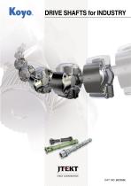
DRIVE SHAFTS for INDUSTRY JTEKT CORPORATION
Open the catalog to page 1
DRIVE SHAFTS for INDUSTRY Throughout the manufacturing industry the pursuit of greater power output at higher efficiency is a priority. Under such circumstances, highly sophisticated and economical drive shafts that fit in a limited space are in great demand for use in various equipment and machines. In response to this demand, JTEKT has renewed its conventional F Series drive shafts and has developed the new CS Series, which feature excellent cost performance, as you will discover in this catalog. Expanded by this new series, Koyo s drive shaft lineup is certain to satisfy your requirements...
Open the catalog to page 2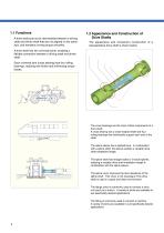
1. Introduction to Drive Shafts A drive shaft acts as an intermediate between a driving shaft and driven shaft that are not aligned on the same axis, and transfers running torque smoothly. A drive shaft has two universal joints, enabling a flexible connection between a driving shaft and driven Each universal joint (cross bearing) has four rolling bearings, realizing low friction and minimizing torque Propeller shafts of construction machines Propeller shafts of diesel locomotives Driving shafts of rolling mills Fig. 1.1 Typical Applications of Drive Shafts Drive Shafts The appearance and component...
Open the catalog to page 3
^DRIVE SHAFTS 1.3 Koyo Drive Shaft Series and Applications Rolling mills Rolling mills D Series, U Series and T Series D Series, U Series and T Series Calender mills Paper mills Drive Shaft Series Lineup Swing diameter Rolling stock Construction machines
Open the catalog to page 4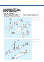
2. Drive Shaft Construction Koyo drive shafts can be classified into two types in construction, depending on the shape of the cross bearings, which serve as universal joints: block type and round type. The features and typical construction of individual types are shown below. 1) Block Type Drive Shafts With the cross bearings fixed by bolts to the yokes, fixing bolts can be greater in size than those of the block type drive shafts transfer torque reliably round type drive shafts, realizing higher capacity. through the key. The rollers, crosses, and bearing
Open the catalog to page 5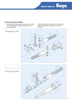
^DRIVE SHAFTS 2) Round Type Drive Shafts Compared with the block type, this type of drive shaft has cross bearings of simpler construction and is more economical. (Joint swing diameter: Up to 180 mm) These drive shafts are connected to machines via a flange, enabling easy connection to a variety of Retainer washer - Flange yoke Cross bearing Weld yoke Propeller tube - Spline shaft (Joint swing diameter: 225 mm or greater) Thrust washer Bearing holder Betainer ring Betainer washer- Propeller tube Flange yoke Cross bearing Weld yoke Spline shaft
Open the catalog to page 6
^DRIVE SHAFTS KO^Oe The individual Koyo drive shaft series are shown below, along with their features and suitable applications. * Characteristics Torque TD : The reference torque used as the criterion for evaluation of resistance to the maximum torque under normal operating conditions. Legends © : Suited TD divided by the maximum torque should preferably be greater than 1.5. O : Applicable Torque Ts : The reference torque used as the criterion for evaluation of resistance to the breaking torque under emergency conditions. A : Used in rare cases Ts divided by the breaking torque should preferably...
Open the catalog to page 7
4. Product Development Systems and Evaluation analysis results ^DRIVE SHAFTS Electron probe microanalyzer Typical analysis result Large sized torsional tester Typical results of evaluation by large sized torsional tester
Open the catalog to page 8
^DRIVE SHAFTS Telescoping Type (with propeller tube) The HW Series is widely used in construction machines and industrial machines. Yoke dimensions are standardized worldwide. A bearing cup is directly fixed to the yoke. The cross bearings and spline construction of basic reference No. 5 thru 12 are very tightly sealed to each other and are useful in severe environments such as muddy water or dust Fixed Type (with propeller tube) Fig. 1 (High wing type) Fig. 1 (High wing type) [Notes] l) TR refers to the rated torque used for service life calculation (refer to page 28). The material factor Km...
Open the catalog to page 9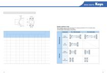
Recommended Dimensions of Coupling Yokes coupling yoke
Open the catalog to page 10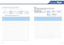
[Notes] l) TE refers to the rated torque used for service life calculation (refer to page 28). The material factor Km is supposed to be 3 in this calculation. 2) TD refers to the reference torque used as the criterion for evaluation of resistance to the maximum torque under normal operating conditions. TD divided by the maximum torque should preferably be greater than 1.5. 3) Ts refers to the reference torque used as the criterion for evaluation of resistance to the breaking torque under emergency conditions. Ts divided by the breaking torque should preferably be greater than 1.5. 4) L refers...
Open the catalog to page 11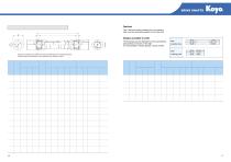
Telescoping Type (with propeller tube) Dimensions marked with an asterisk (*) need to be determined to suit existing equipment. Please provide the specifications of your equipment when placing an inquiry. [Notes] l) refers to the rated torque used for service life calculation (refer to page 28). The material factor Km is supposed to be 3 in this calculation. 2) TD refers to the reference torque used as the criterion for evaluation of resistance to the maximum torque under normal operating conditions. TD divided by the maximum torque should preferably be greater than 1.5. 3) Ts refers to the reference...
Open the catalog to page 12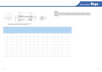
^DRIVE SHAFTS The T Series is intended for such applications where telescoping function is required in a small space. Because one of the cross bearings needs to be hollow to enable the required stroke, this series is applicable in such cases where the swing diameter has a given allowance on either the driving side or driven side. Dimensions marked with an asterisk (*) need to be determined to suit existing equipment. Please provide the specifications of your equipment when placing an inquiry. [Notes] 1) TE refers to the rated torque used for service life calculation (refer to page 28). The material...
Open the catalog to page 13
^DRIVE SHAFTS Telescoping Type (with propeller tube) Fixed type (with propeller tube) Fixed type (with double flanges) [Notes] l) refers to the rated torque used for service life calculation (refer to page 28). The material factor Km is supposed to be 3 in this calculation. 2) TD refers to the reference torque used as the criterion for evaluation of resistance to the maximum torque under normal operating conditions. TD divided by the maximum torque should preferably be greater than 1.5. 3) Ts refers to the reference torque used as the criterion for evaluation of resistance to the breaking torque...
Open the catalog to page 14All JTEKT catalogs and technical brochures
 ONI Flyer
2 Pages
 EasyFit NC-Ball Bearing Units
16 Pages
 Ball Bearing Units
2 Pages
 Ball & Roller Bearings
397 Pages
 INSERT BEARING UNITS
194 Pages
 Spherical Roller Bearings
8 Pages
 Ceramic bearings
17 Pages
 B1011E Traction Drive Unit
4 Pages
 B1005E EXSEV Product Guidebook
13 Pages
 Agriculture and Construction
6 Pages
 catb2018e
272 Pages
 Ball & Roller Bearings
80 Pages
 Ceramic&Exsev bearing
87 Pages
 OIL SEALS & O-RINGS
129 Pages
 TAPERED ROLLER BEARINGS
83 Pages
 LARGE SIZE BALL & ROLLER BEARINGS
245 Pages


Archived catalogs
 Needle Roller Bearings
274 Pages
 NEEDLE ROLLER BEARINGS_2010
158 Pages
 CERAMIC & EXSEV BEARINGS
70 Pages
 Ball Bearing Units
194 Pages
 Ball & Roller Bearings
200 Pages
 High Performance Bearings
6 Pages
 Miniature Bearings
71 Pages
 Miniature One Way Clutch
6 Pages
 Roll Neck Bearings
8 Pages
 Sprag Clutches
19 Pages
 Exsev Bearings
19 Pages
 Ceramic Bearings
6 Pages
 Oil Seals & O-Rings
119 Pages

