


Ball & Roller Bearings

Ball & Roller Bearings
- Structures and Types: Bearings consist of rings, rolling elements, and a cage. They are classified by the number of rows (single, double, multi-row) and by type (radial or thrust) based on the contact angle.
- Selection Guidelines: Includes criteria for selecting bearing type, arrangement, dimensions, and fits. It covers service life calculations, load assessments, and dynamic/static load ratings.
- Tolerances and Speeds: Details on bearing tolerances, limiting speeds, and considerations for high-speed applications.
- Internal Clearance and Preload: Guidelines for selecting internal clearance and methods for preloading to enhance rigidity and performance.
- Lubrication: Discusses the purpose, methods, and types of lubricants suitable for different bearing applications.
- Materials: Information on materials used for bearing rings, rolling elements, and cages, emphasizing durability and performance.
- Shaft and Housing Design: Recommendations for accuracy, roughness, and sealing devices in shaft and housing design.
- Handling and Maintenance: Instructions for storage, mounting, dismounting, and maintenance of bearings, including failure analysis methods.
This section describes various types of bearings, including those with flat back faces, spherical back faces, and aligning seat races. Bearings are categorized based on their ability to accommodate axial loads in one or both directions. Bearings with spherical back faces are self-aligning, which helps compensate for mounting errors. Recommended cage materials include pressed steel, copper alloy, and synthetic resin. Main applications include automobile king pins and machine tool spindles.
These bearings consist of washer-shaped rings and cylindrical roller and cage assemblies. They accommodate axial loads in one direction and offer great axial load resistance and high rigidity. Recommended for use in oil excavators and steel equipment.
Available in separable and non-separable types, these bearings are compact and contribute to size reduction in application equipment. They accommodate axial loads in one direction and are used in transmissions for automobiles and machine tools.
These bearings feature tapered rollers and can accommodate axial loads in one or both directions. They are used in crane hooks and rolling mill roll necks. Copper alloy machined cages are recommended.
These bearings are self-aligning and can accommodate both axial and small radial loads. They are typically used in hydroelectric generators and vertical motors.
The selection process involves considering installation space, load magnitude, rotational speed, running accuracy, rigidity, misalignment, and mounting ease. The goal is to select the right bearing to achieve optimum performance. Factors such as operating conditions, performance requirements, and cost performance are considered.
Key factors include installation space, load type and direction, rotational speed, running accuracy, rigidity, misalignment, and mounting/dismounting methods. Different bearing types are compared based on these factors to determine the most suitable option for specific applications.
Typically, two or more bearings are used on one shaft to locate shaft positions in the axial direction. One bearing is mounted on the fixed side, and another on the free side. The arrangement depends on the operational conditions and performance requirements of the bearings.
This section outlines the different types of bearings used for fixed and free sides, as well as for vertical shafts. Fixed side bearings determine shaft axial position and accommodate both radial and axial loads. Examples include deep groove ball bearings and spherical roller bearings. Free side bearings compensate for expansion or shrinkage due to temperature changes and typically accommodate radial loads only. Examples include cylindrical roller bearings and needle roller bearings. For vertical shafts, bearings that can handle both radial and axial loads are recommended on the fixed side, while radial load-only bearings are used on the free side.
Various bearing arrangements are recommended based on application requirements such as speed, load, and potential for mounting errors. For instance, arrangement Ex. 1 is suitable for high-speed operations, while Ex. 3 is recommended for heavier impact loads. Each example provides guidance on the appropriate fixed and free side bearings and their applications, such as motors, pumps, and steel manufacturing equipment.
This section discusses the factors affecting bearing service life, including material fatigue and other failure modes like wear and seizure. The basic dynamic load rating is defined, which is crucial for determining the bearing's capacity under rolling fatigue. Equations are provided to calculate the basic rating life in terms of revolutions, time, or distance, depending on the application. The section also covers the correction of load ratings for high-temperature use and the importance of dimension stabilizing treatment.
The document provides formulas for calculating the basic dynamic load rating and the corrected rating life, considering factors like temperature and material treatment. The corrected rating life is essential for applications requiring reliability greater than 90%. Special materials and lubrication can extend bearing life, and the document emphasizes the importance of selecting the appropriate bearing dimensions based on these calculations.
The document discusses the importance of considering the reliability of shaft and housing in bearing systems. It introduces the reliability coefficient (a1), which is used to calculate the corrected rating life for reliability greater than 90%. The reliability coefficient varies with temperature, affecting the bearing's corrected rating life.
Bearing Characteristic Coefficient (a2)
The bearing characteristic coefficient (a2) accounts for variations in bearing materials and production processes. JTEKT uses vacuum-degassed bearing steel, which extends bearing life. For special materials, a2 is greater than 1.
Operating Condition Coefficient (a3)
The operating condition coefficient (a3) adjusts for conditions affecting bearing life, such as lubrication quality. Under normal lubrication, a3 is 1, but it can be greater than 1 under favorable conditions. If lubrication is poor, a3 is less than 1.
Service Life of Bearing Systems
For systems with multiple bearings, the service life is determined by the bearing with the shortest life. The document provides an equation for calculating the system's rating life.
Recommended Bearing Service Life
The document provides a table of recommended service life for various applications, ranging from household appliances to industrial equipment, based on operating conditions.
Load Calculations
Loads affecting bearings include forces from supported objects and transmission devices. The document explains how to calculate these loads using coefficients to account for fluctuations and impacts.
Load Coefficients
Load coefficients adjust theoretical load values to account for operational conditions. The document provides tables for load coefficients in different scenarios, such as belt and chain transmissions.
Gear Load Calculations
In gear transmissions, loads are classified into tangential, radial, and axial loads. The document provides equations and coefficients for calculating these loads, considering gear type and operational impacts.
Load Distribution on Bearings
The document explains how to calculate load distribution on bearings, considering radial and axial forces. It provides examples of load distribution calculations for different scenarios.
The dynamic equivalent load (P) is a theoretical load that provides the same bearing service life as the actual load and rotational speed. It is calculated for radial and thrust bearings receiving combined loads. For single-row radial bearings, if Fa/Fr ≤ e, X = 1 and Y = 0, making Pr = Fr. For angular contact ball bearings and tapered roller bearings, axial component forces are considered, and a pair of bearings is arranged face-to-face or back-to-back. The dynamic equivalent load is calculated using P = XFr + YFa.
When load magnitude or direction varies, the mean dynamic equivalent load (Pm) is calculated to provide the same bearing service life as under actual load fluctuations. It is determined using graphs and equations, considering staged and stageless fluctuations, and simultaneous stationary and rotating loads.
The basic static load rating is the static load that causes a specific contact stress at the contact center between the raceway and rolling elements. The static equivalent load is a theoretical load that generates the same contact stress as the actual loading condition. It is calculated for radial and thrust bearings using specific equations.
The safety coefficient ensures safety in relation to the basic static load rating, based on empirical data. It varies depending on the operating conditions and is listed in Table 5-9.
Cylindrical roller bearings can accommodate axial loads, controlled by roller conditions, rib load capacity, lubrication, and rotational speed. The maximum allowable axial load is calculated using empirical data and specific coefficients.
Examples are provided for calculating bearing service life with different reliability percentages, total revolutions, and bearing size selection. These examples illustrate the application of the discussed equations and concepts in practical scenarios.
The document provides detailed calculations and specifications for selecting bearings based on load ratings and service life requirements. It includes examples of bearing size selection and calculation of allowable axial loads for different types of bearings, such as deep groove ball bearings and cylindrical roller bearings. The calculations involve determining dynamic equivalent loads, basic dynamic load ratings, and basic rating life using specified equations and interpolation methods.
Examples and Procedures:
Several examples illustrate the process of selecting appropriate bearings based on given conditions, such as rotational speed, radial and axial loads, and required service life. The document explains how to calculate the dynamic equivalent load and basic rating life for different bearing types, using specific equations and coefficients from tables.
Standards and Dimensions:
The document references international standards, such as ISO and JIS, for bearing boundary dimensions. It explains the importance of these dimensions for bearing installation and provides tables listing the dimensions for various bearing types, including radial, tapered roller, and thrust bearings.
Bearing Numbers and Codes:
The document describes the composition of bearing numbers, which include a basic number and supplementary codes indicating specifications like bearing type, dimensions, and internal clearance. Examples of bearing numbers are provided, along with explanations of the codes used.
Key Data and Tables:
The document includes tables and figures that provide essential data for calculations, such as load coefficients, dimension series, and bearing series codes. These tables are crucial for selecting the correct bearing and ensuring it meets the specified requirements.
The document provides detailed specifications for various types of bearings, including thrust ball bearings, spherical thrust roller bearings, and radial bearings. Key parameters include nominal bore diameter (d), nominal outside diameter (D), nominal inner ring width (B), nominal outer ring width (C), and nominal assembled bearing width (T).
Procedures:
Measurement methods for dimensional and running accuracy are outlined, referencing JIS B 1515 standards. Specific procedures for measuring bore diameter, both cylindrical and tapered, as well as outside diameter, are included.
Norms and Standards:
The document adheres to JIS B 1514-2 and JIS B 1514-3 standards, detailing tolerances for different bearing types. It includes tables specifying permissible deviations and variations for bore and outside diameters, as well as bearing height.
Recommendations:
Recommendations are provided for applying tolerances to specific bearing types, such as thrust ball bearings and cylindrical roller thrust bearings with a 90° contact angle. The document also advises on the application of tolerances to radial bearings with tapered bores and flanged radial ball bearings.
Key Data from Tables:
Tables in the document specify tolerances for various bearing dimensions, including shaft race, housing race, and bearing height. For example, tolerances for nominal bore diameters range from 0 to -100 μm, depending on the size class. The tables also provide permissible values for chamfer dimensions and flange widths.
Critical Information:
Critical parameters include the maximum permissible deviations for bore and outside diameters, as well as the specific tolerances for different bearing classes (0, 6, 5, 4). The document emphasizes the importance of adhering to these tolerances to ensure proper bearing function and longevity.
The document outlines the methods for measuring and calculating various diameters and deviations in bearings. The bore diameter (ds) and outside diameter (Ds) are measured in a single radial plane to determine maximum (dsp max, Dsp max) and minimum values (dsp min, Dsp min). The mean bore diameter (dmp) and mean outside diameter (Dmp) are calculated as the arithmetic mean of these values. Deviations and variations are also calculated for both bore and outside diameters.
Dimensional Accuracy:
Details are provided on the dimensional accuracy of roller set bore diameter (Fw), outside diameter (Ew), and ring widths (B, C). Deviations from nominal dimensions are calculated for these components.
Running Accuracy:
Running accuracy is assessed through radial and axial runout measurements of inner and outer rings. These are obtained by measuring the difference between maximum and minimum readings during rotation.
Limiting Speed:
The limiting speed of bearings is discussed, which is the maximum speed at which a bearing can operate without excessive heat generation. Factors affecting limiting speed include bearing type, dimensions, lubrication, and load conditions. Correction coefficients are used to adjust limiting speed based on load magnitude and combined load.
Frictional Coefficient:
The frictional moment of rolling bearings is compared to plain bearings, with reference values provided for different bearing types. The friction coefficient depends on bearing type, load, speed, and lubrication.
Bearing Fits:
The purpose of fits is to prevent detrimental sliding (creep) by securely fixing the bearing rings to the shaft or housing. Tolerances for shaft and housing diameters are standardized, and fit selection is based on load characteristics, temperature distribution, and other factors. Load characteristics are classified into rotating inner ring load, rotating outer ring load, and indeterminate direction load, with corresponding fit recommendations.
This document provides detailed technical specifications and guidelines for fitting bearings, focusing on the effects of interference, surface roughness, temperature, and stress on bearing performance. It includes equations and tables to calculate the necessary interference and stress levels for optimal bearing function.
Interference is crucial for bearing performance, and its effectiveness can be reduced by bore enlargement or temperature differences. The document provides equations to calculate interference reduction and highlights the need for greater interference when radial loads exceed 25% of the basic static load rating or when impact loads are expected.
The effective interference after fitting can differ from calculated values due to surface roughness and plastic deformation. Temperature differences between the bearing and its surroundings can also reduce interference, necessitating adjustments based on the thermal expansion of materials.
Excessive stress from interference fitting can lead to bearing ring fractures. The document advises keeping maximum interference below 1/1000 of the shaft diameter and stresses below 120 MPa. It also discusses the need for different interference levels based on material properties and housing types.
Tables provide standard and recommended fits for various bearing types and conditions, including radial and thrust bearings. These recommendations consider load characteristics, temperature, and mounting methods, with specific fits for different shaft and housing materials.
Additional guidelines are provided for high-accuracy applications, hollow shafts, thin-section housings, and materials like aluminum. The document emphasizes consulting with JTEKT for specific cases and provides detailed tables for precision fits in various applications.
The document provides detailed specifications for various types of bearings, including ball bearings, roller bearings, and needle roller bearings. It outlines the average diameter of rolling elements for ball bearings (approximately 0.3 times the difference between the outer and inner diameters) and roller bearings (approximately 0.25 times the difference).
Temperature Rise:
Temperature rise parameters are defined for the inner ring (ti), outer ring (te), and rolling elements (tw).
Bearing Internal Clearance:
The document extensively covers the radial and axial internal clearances for different types of bearings, including deep groove ball bearings, extra-small/miniature ball bearings, angular contact ball bearings, and cylindrical roller bearings. It provides tables with clearance values in micrometers (μm) for various nominal bore diameters.
Tables and Data:
Several tables are included, such as:
- Table 10-2: Radial internal clearance of deep groove ball bearings.
- Table 10-3: Radial internal clearance of extra-small/miniature ball bearings.
- Table 10-4: Axial internal clearance of matched pair angular contact ball bearings.
- Table 10-5 to 10-11: Various tables detailing radial internal clearances for different bearing types and configurations.
Correction Factors:
Correction factors for measured clearance due to measurement load are provided, indicating adjustments needed for accurate clearance values.
Standards and Remarks:
Some values are prescribed by JTEKT standards, and remarks are included to guide the application of correction factors and the relationship between radial and axial clearances.
The document provides detailed specifications and procedures for selecting and applying preload to bearings, particularly angular contact ball bearings and tapered roller bearings. It includes tables with dimensional tolerances for shafts and housing bores, as well as recommended preload amounts for various applications.
Service Conditions and Applications:
Different service conditions and applications are outlined, such as heavy/impact loads, vibration, and shaft deflection. Specific examples include railway rolling stock axle journals and automobile rear wheels, with corresponding clearance selections like C3, C4, and C5.
Preload Purpose and Methods:
The purpose of preload is to improve running accuracy, gear engagement, and minimize noise and vibration. Methods of preloading include position preloading and constant pressure preloading, each with specific advantages depending on the application requirements.
Preload and Rigidity:
The document explains the relationship between preload and rigidity, particularly in back-to-back arrangements for angular contact ball bearings. It includes diagrams illustrating the effects of preload on displacement and rigidity.
Recommended Fits and Preload Amounts:
Tables provide recommended fits for high-precision matched pair angular contact ball bearings with preload applied. Preload amounts are categorized into slight, light, medium, and heavy, with specific recommendations for different machine tool spindles and applications.
Key Formulas and Definitions:
Several formulas are provided for calculating axial and radial internal clearances, as well as preload amounts. Definitions for terms like axial load, radial load, and contact angle are included to aid in understanding the calculations.
Spherical thrust roller bearings can experience defects due to sliding between the roller and raceway surface. To prevent this, the bearing should be mounted without clearance and an axial load (preload) greater than the minimum necessary should be applied. The minimum necessary axial load is determined by two equations, and the higher value should be used.
Lubrication is crucial for bearing performance, affecting friction, wear, heat dissipation, and contamination prevention. There are two main types of lubrication: grease and oil.
Grease lubrication is advantageous due to its long-lasting nature and simple structure. It can be applied using closed or feeding methods. The amount of grease should generally fill one-third to one-half of the space, but can be more for low-speed operations to prevent contamination. Regular replenishment is necessary, and clean grease should be used.
Oil lubrication is suitable for high-speed and high-temperature conditions, reducing vibration and noise. Various methods include oil bath, oil drip, oil splash, forced oil circulation, oil jet, oil mist, and oil/air lubrication. Each method has specific applications and benefits, such as cooling effects and ease of maintenance.
Grease life can be estimated using specific equations, considering factors like operating temperature and load conditions. Regular intervals for grease feeding are recommended based on rotational speed and temperature corrections.
Different oil lubrication methods are detailed, including their suitability for various speeds and loads. Forced oil circulation and oil jet lubrication are highlighted for high-speed applications, while oil mist lubrication is noted for its efficiency in high-speed rotation bearings.
1. JIS G 3131 SPHC: Maximum carbon content of 0.15%, manganese not exceeding 0.60%, and sulfur and phosphorus both limited to 0.050%.
2. BAS 361 SPB 2: Carbon content ranges from 0.13 to 0.20%, with sulfur and phosphorus not exceeding 0.030%.
3. JIS G 4305 SUS 304: Maximum carbon content of 0.08%, manganese up to 2.00%, and chromium content between 18.00 to 20.00%.
1. Shafts should be thick and short to minimize distortion.
2. Housings must have sufficient rigidity to reduce load-induced distortion.
3. The fitting surfaces should be finished for accuracy and roughness, with perpendicular shoulder end-faces.
4. Fillet radius should be smaller than the bearing chamfer dimension.
5. Shoulder height should facilitate easy bearing dismounting.
6. Use spacers if fillet radius or shoulder height adjustments are needed.
7. Threads and lock nuts should be perpendicular to the shaft axis.
8. Split housings should have smooth meeting surfaces with recesses.
Recommended accuracy and roughness for shafts and housings are provided, with specific tolerances for roundness, cylindrical form, and shoulder runout.
Includes necessary dimensions for mounting bearings, such as fillet radius and shoulder diameters, with standard values provided.
Examples of mounting designs for cylindrical and tapered bore bearings are provided, including methods like shaft locknut, end plate, and adapter assembly.
1. Non-contact Sealing Devices: Include oil grooves, flingers, and labyrinths, suitable for high-speed and high-temperature operations.
2. Contact Sealing Devices: Utilize synthetic rubber or resin for sealing, with oil seals being the most common type.
In environments where dirt or water penetration is expected, it is recommended to use two oil seals together or fill the space between the sealing lips with grease. Different seal materials have varying properties, affecting allowable lip speed and operating temperature. Proper material selection allows oil seals to be used for sealing lubricants and chemicals. Key shaft conditions for optimal sealing include specific material, surface hardness, and roughness.
Felt Seals and Alternatives
Felt seals are traditionally used but are recommended to be replaced with rubber oil seals due to limited conditions of use. JTEKT offers a range of oil seals for various applications, including automotive and industrial uses.
Handling of Bearings
Bearings require careful handling due to their precision. Key instructions include maintaining cleanliness, using proper tools, protecting from rust, and ensuring experienced operators handle them. Storage conditions should prevent corrosion, and bearings should be stored at specific humidity and temperature levels.
Bearing Mounting Procedures
Preparation before mounting includes inspecting shafts and housings for flaws and ensuring dimensions meet specifications. Mounting methods vary based on bearing type and fitting conditions, with interference fits applied differently depending on whether the shaft or outer ring rotates. Press fit and shrink fit methods are detailed, with specific instructions for heating and cooling bearings.
Test Run and Inspection
A trial operation ensures proper mounting, starting with manual checks for compact machines and progressing to power operation. Abnormalities such as knocking or excessive torque should be addressed before full operation. Bearings should rotate smoothly without abnormal vibration or noise.
Discoloration of the raceway and other surfaces can be caused by insufficient lubrication, improper internal clearance, or lubricant quality deterioration. To address these issues, improve sealing devices, ensure proper internal clearance, and select appropriate lubricants.
Scratches are shallow marks from sliding contact, while scuffing involves partial melting due to high pressure. Causes include insufficient lubrication and careless handling. Countermeasures include applying lubricant during mounting and improving mounting procedures.
Smearing involves minute seizures on rolling contact surfaces due to high temperatures. It is caused by improper lubrication and slipping of rolling elements. Solutions include selecting proper lubricants and providing proper preload.
Rust and corrosion result from chemical reactions on metal surfaces, often due to improper storage or contamination. Preventive measures include improving storage conditions, sealing devices, and applying rust preventive treatments.
Electric pitting occurs when electric currents pass through bearings, causing surface melting. Solutions include providing a bypass to prevent current flow through bearings and insulating bearings.
Wear affects sliding contact surfaces and can be exacerbated by foreign matter and corrosion. Countermeasures include selecting proper lubricants, improving sealing devices, and cleaning bearings.
Fretting occurs due to vibration in stationary bearings, characterized by rust-colored wear particles. Solutions include providing greater interference and applying lubricant to fitting surfaces.
Creeping involves movement of bearing rings relative to the shaft or housing. It is caused by insufficient interference or tightening. Solutions include providing greater interference and proper sleeve tightening.
Cages can suffer from flaws, distortion, and excessive wear due to external pressure and improper mounting. Countermeasures include re-examining load conditions, selecting proper lubricants, and minimizing mounting deviation.
Seizure is caused by abnormal heating, leading to discoloration and distortion. It results from small internal clearance, improper lubrication, or excessive load. Solutions include providing proper internal clearance and selecting appropriate lubricants.
Catalog excerpts

|| JTEKT Koyo Ball & Roller Bearings || Ball & Roller Bearings Ball & Roller Bearings Ball & Roller Bearings CAT. NO. B 2 0 01 E - 4 Printed i n Japa n '12. 0 7 - 3 CDS ('06 . 1) CAT. NO. B2001E-4 CAT. NO. B 2 0 01 E - 4
Open the catalog to page 1
1 Structures and types ⋅⋅⋅⋅ A 1 4 Selection of arrangement ⋅⋅⋅⋅⋅⋅⋅⋅ A 20 7 Tolerances ⋅⋅⋅⋅⋅⋅⋅⋅⋅⋅⋅⋅⋅⋅⋅⋅⋅⋅⋅⋅⋅⋅⋅⋅⋅⋅⋅⋅ A 52 10 Internal ⋅⋅⋅⋅⋅⋅⋅⋅⋅⋅⋅ A 93 clearance 13 Materials ⋅⋅⋅⋅⋅⋅⋅⋅⋅⋅⋅⋅⋅⋅⋅⋅⋅⋅⋅ A 122 2 Outline of selection ⋅⋅⋅⋅⋅⋅⋅ A 14 5 Selection of dimensions ⋅⋅⋅⋅⋅⋅⋅⋅⋅⋅ A 24 8 Limiting speed ⋅⋅⋅⋅⋅⋅⋅⋅⋅⋅⋅⋅⋅⋅⋅⋅⋅⋅⋅⋅⋅ A 78 11 Preload ⋅⋅⋅⋅⋅⋅⋅⋅⋅⋅⋅⋅⋅⋅ A 106 14 Shaft and housing design ⋅⋅⋅⋅⋅⋅⋅⋅ A 125 3 Selection of type ⋅⋅⋅⋅⋅⋅⋅⋅⋅⋅⋅⋅ A 16 Boundary dimensions ⋅⋅⋅⋅⋅⋅⋅⋅⋅⋅⋅⋅⋅⋅ A 46 and bearing numbers 9 Fits ⋅⋅⋅⋅⋅⋅⋅⋅⋅⋅⋅⋅⋅⋅⋅⋅⋅⋅⋅⋅⋅⋅⋅⋅⋅⋅⋅⋅⋅⋅⋅⋅⋅⋅⋅⋅⋅⋅⋅⋅⋅ A 80 12 Lubrication ⋅⋅⋅⋅⋅⋅⋅⋅ A 111 15 Handling ⋅⋅⋅⋅⋅⋅⋅⋅⋅⋅⋅⋅⋅⋅⋅⋅⋅⋅⋅...
Open the catalog to page 2
BALL & ROLLER BEARINGS CAT. NO. B2001E-4
Open the catalog to page 3
Publication of Rolling Bearing Catalog Today’s technology-based society, in order to utilize the earth’s limited resources effectively and protect the environment, must strive to develop new technologies and alternate energy sources, and in that connection it continues to pursue new targets in various fields. To achieve such targets, technically advanced and highly functional rolling bearings with significantly greater compactness, lighter weight, longer life and lower friction as well as higher reliability during use in special environments are sought. This new-edition catalog is based on the...
Open the catalog to page 4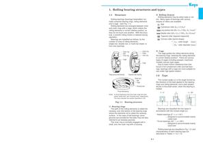
1. Rolling bearing structures and types 1-1 Structure 2) Rolling element Rolling elements may be either balls or rollers. Many types of bearings with various shapes of rollers are available. Ball Cylindrical roller (LW ≤ 3 DW)* Rolling bearings (bearings hereinafter) normally comprise bearing rings, rolling elements and a cage. (see Fig. 1-1) Rolling elements are arranged between inner and outer rings with a cage, which retains the rolling elements in correct relative position, so they do not touch one another. With this structure, a smooth rolling motion is realized during operation. Bearings...
Open the catalog to page 6
3 !• Rolling bearing structures and types \ ball bearing , Radial bearing -Deep groove ball bearing -Angular contact ball bearing ball bearing ball bearing Single-row Matched pair Radial ) roller bearing roller bearing Rolling bearing roller bearing roller bearing Single-row Double-row Single-row Double-row Single-row Double-row ball bearing Thrust bearing ball bearing -Angular contact ball bearing Single [with aligning direction seat race Double [with aligning" direction seat races roller bearing -Cylindrical roller thrust bearing -Needle roller thrust bearing -Tapered roller thrust bearing...
Open the catalog to page 7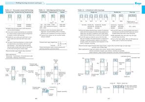
1. Rolling bearing structures and types Four-point contact ball bearings Table 1-4 One-piece type Two-piece inner ring Two-piece outer ring Self-aligning ball bearings Cylindrical bore 6200BI 6300BI 2RS 120, 130 11200, 11300 ⋅⋅⋅ 1200, 1300 extended inner ring type 2200, 2300 (6200BO) (6300BO) ■ Radial load and axial load in both directions can be accommodated. 2200 2RS 2300 2RS ■ Spherical outer ring raceway allows selfalignment, accommodating shaft or housing deflection and misaligned mounting conditions. ■ A four-point contact ball bearing can substitute for a face-to-face or back-to-back arrangement...
Open the catalog to page 9
1. Rolling bearing structures and types Table 1-6 Machined ring needle roller bearings Table 1-7 Single-row Double-row Tapered roller bearings Single-row Double-row Flanged type With inner ring Without inner ring Sealed With inner ring Without inner ring NA4900 NA5900 (NQI, NQIS) RNA4900 RNA5900 (NQ, NQS) NA4900UU − NA6900 RNA6900 ■ In spite of their basic structure, which is the same as that of NU type cylindrical roller bearings, bearings with minimum ring sections offer space savings and greater resistance to radial load, by using needle rollers. ■ Bearings with no inner rings function using...
Open the catalog to page 10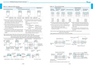
1. Rolling bearing structures and types Table 1-8 Spherical roller bearings Table 1-9 Cylindrical bore Convex asymmetrical roller type Tapered bore Convex symmetrical roller type R, RR RH, RHR ■ This type can accommodate radial load and axial load in both directions, which makes it especially suitable for applications in which heavy load or impact load is applied. With spherical back face Double direction With aligning seat race With flat back faces Convex symmetrical roller With aligning seat races ■ The tapered bore type can be easily mounted/ dismounted by using an adapter or withdrawal sleeve....
Open the catalog to page 11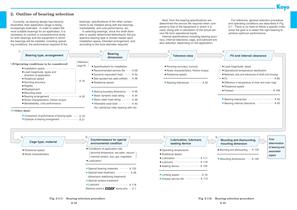
2. Outline of bearing selection bearings, specifications of the other components to be installed along with the bearings, marketability, and cost performance, etc. In selecting bearings, since the shaft diameter is usually determined beforehand, the prospective bearing type is chosen based upon installation space, intended arrangement, and according to the bore diameter required. Currently, as bearing design has become diversified, their application range is being increasingly extended. In order to select the most suitable bearings for an application, it is necessary to conduct a comprehensive...
Open the catalog to page 13All JTEKT catalogs and technical brochures
 ONI Flyer
2 Pages
 EasyFit NC-Ball Bearing Units
16 Pages
 Ball Bearing Units
2 Pages
 Ball & Roller Bearings
397 Pages
 INSERT BEARING UNITS
194 Pages
 Spherical Roller Bearings
8 Pages
 Ceramic bearings
17 Pages
 B1011E Traction Drive Unit
4 Pages
 B1005E EXSEV Product Guidebook
13 Pages
 Agriculture and Construction
6 Pages
 catb2018e
272 Pages
 DRIVE SHAFTS for INDUSTRY
25 Pages
 Ceramic&Exsev bearing
87 Pages
 OIL SEALS & O-RINGS
129 Pages
 TAPERED ROLLER BEARINGS
83 Pages
 LARGE SIZE BALL & ROLLER BEARINGS
245 Pages


Archived catalogs
 Needle Roller Bearings
274 Pages
 NEEDLE ROLLER BEARINGS_2010
158 Pages
 CERAMIC & EXSEV BEARINGS
70 Pages
 Ball Bearing Units
194 Pages
 Ball & Roller Bearings
200 Pages
 High Performance Bearings
6 Pages
 Miniature Bearings
71 Pages
 Miniature One Way Clutch
6 Pages
 Roll Neck Bearings
8 Pages
 Sprag Clutches
19 Pages
 Exsev Bearings
19 Pages
 Ceramic Bearings
6 Pages
 Oil Seals & O-Rings
119 Pages

