Group: JTEKT Corporation

Catalog excerpts

INSTALLATION AND MAINTENANCE MANUAL FOR ROLLING MILL BEARINGS (2) FOUR-ROW CYLINDRICAL ROLLER BEARINGS (Cylindrical Bore) FOR ROLL NECKS
Open the catalog to page 1
★The contents of this installation and handling manual are subject to change without prior notice. Every possible effort has been made to ensure that the data listed in this catalog is correct. However, we cannot assume responsibility for any errors or omissions. Reproduction of this installation and handling manual without written consent is strictly prohibited.
Open the catalog to page 2
Although various types of roll neck bearings are used, four row cylindrical roller bearings with cylindrical bore, mounted with interference fits, are widely used for the rolls of heavy loaded, high precision or high speed rolling mills. As the roll nock bearing is manufactured to a very high degree of precision, it must be handled with a corresponding degree of carefulness. Otherwise, even an ideally designed and most accurately manufactured bearing can not function as designed and in extreme cases, unexpected operating problems might be resulted. Therefore, the personnel in charge of...
Open the catalog to page 3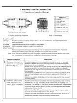
1-1 Preparation and Inspection of Bearings General Precautions 1) Storage Keep bearings and surroundings clean and store in a dry, cool and dark place, Avoid high temperature and 2) Handling Carefully handle bearings and do not subject to heavy impacts 3) Packaging Do not unpack until installation in case of brand new bearing 4) Rust Preventive Oil Remove rust preventive oil thoroughly from bearings when the bearings are oil-mist-lubricated. Pay special attention when washing cages, outer rigns, oil holes in outer rings and outer ring spacer. (Note) When bearings are lubricated...
Open the catalog to page 4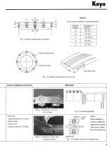
Koyo VG-10-1 Serial number and Row number (Example) Marked location Fig. 1-3 Loaded zone marking on outer ring Remarks >. 2 5 <D I | o E to co CC TO Photo. 1-2 Serial No. and row No. of cage Oil stone (approximately No. 500 grit) Microgrinder Emery cloth (approximately No. 200 grit) (Note) Area indicated by arrows is called the loaded zone and the other area is called the non-loaded zone
Open the catalog to page 5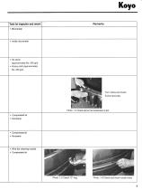
Remarks • Inside micrometer (approximately No. 500 grit) • Emery cloth (approximately No. 200 grit) Koyo Turn rollers and check if pins have play Photo. 1-4 Check abnormal looseness of
Open the catalog to page 7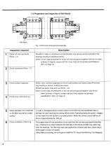
Fig. 1-6 Roll and chock general assembly
Open the catalog to page 8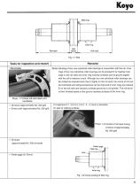
Tools for inspection and rework Remarks Photo. 1-7 Check roll neck taper and roundness Oil stone (approximately No. 500 grit) A roughness of 1.5 S to 3. 0 S (1. 5 - 3. 0pm) is desirable Emery cloth (approximately No. 200 grit) for seal l!P rubbing surfaces (Note) Grinding of four row cylindrical roller bearings in conjunction with the roll. Inner rings of four row cylindrical roller bearings can be pressed fit by heating inner rings on the roll neck and inner ring raceway surfaces can be ground togeter with the roll to improve runout. Although four row cylindrical roller bearings can be...
Open the catalog to page 9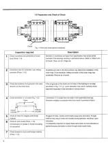
1-3 Preparation and Check of Chock
Open the catalog to page 10
Tools for inspection and rework Remarks Inside micrometer Oil stone (approximately No. 500 grit) Emery cloth (approximately No. 200 grit) • Vernier calipers • Feeler gage • Shims • Compressed air • Oil stone (approximately No. 500 grit)
Open the catalog to page 11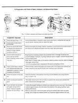
Fig. 1-13 Seals, outboard, and inboard end plates assembly
Open the catalog to page 12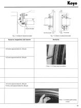
Fig. 1-15 Detail of outboard end plate
Open the catalog to page 13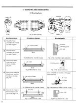
Mounting procedureProcedure diagram Mounted parts Mount No. 1 seal (oil seal) on the inboard end plate (Fig. 2-4) Mount No. 2 seal (oil seal) on the inboard end plate (Fig. 2-4) Mount the No. 3 seal (water seal) on the inboard end plate (Fig. 2-7) Mount the No. 4 and No. 5 seals (scale seals) on the inboard end plate (Fig. 2-9) Mount the No. 1 seal in the outboard end plate (thrust side) (Fig. 2-11)
Open the catalog to page 14
Fig. 2-2 Detail of inboard end plate assembly Fig. 2-3 Detail of outboard end plate assembly
Open the catalog to page 15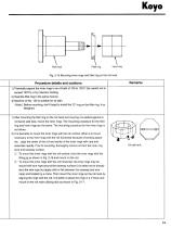
Procedure details and cautions 1) Thermally expand the inner rings in an oil bath of 100 to 120°C (be careful not to exceed 120°C) or by induction heating. 2) Heat the fillet ring in the same manner. 3) Machine oil No. 150 is suitable for oil bath. (Note) Before mounting, don’t forget to install the “O” ring on the fillet ring, if so designed. 1) After mounting the fillet ring on the roll neck and insuring it is seated against to roll barrel side face, mount the inner rings. The mounting procedure for the fillet ring and inner rings are the same. The mounting procedure for the inner rings...
Open the catalog to page 16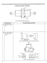
Mounting procedure Procedure diagram and photo Heat fillet ring and inner rings Mount fillet ring first then inner rings on the roll neck (1) Fig. 2-17 Inner ring mounting rail
Open the catalog to page 17
Mounting procedure Procedure diagram and photo Mounting procedure Procedure diagram and photo Mount inner rings on roll neck (2) Copper or alminum alloy Trapezoidal thread ® Detail of pushing jig Fig. 2-18 Driving inner rings on Gnnding of roll barrel
Open the catalog to page 18
2-3 Mounting Bearing into the Inboard End Plate and Chock Procedure diagram and photo Mounting procedure Attach inboard end to chock (Fig. 2-24) Install loose rib (side ring) into chock (Fig. 2-25)
Open the catalog to page 20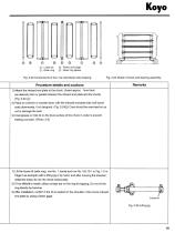
Procedure details and cautions Attach the inboard end plate to the chock. (Insert approx. 1mm thick (as desired) shim or gasket between the inboard end plate and the chock) (Fig. 2-24®) Place on a bench or wooden bars, with the inboard end plate side (roll barrel side) downwards, if so designed. (Fig. 2-24(§)) Care should be exercised so as not to damage the seal. Coat grease or mist oil on the bore surface of the chock in order to prevent fretting corrosion. (Photo. 2-2) 1) Lift the loose rib (side ring), row No. 1 (serial and row No. VG-10-1 in Fig. 1-2 in Page 2 as example) with a...
Open the catalog to page 21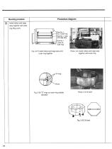
Mounting procedure Procedure diagram assy together with outer Photo. 2-4 Install rollers and cage assy together with outer ring
Open the catalog to page 22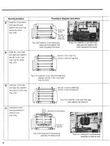
Mounting procedure Procedure diagram and photo Install No. 2 row rollers and cage assy and together with outer ring spacer into chock (Fig. 2-30) and cage assy together with No. 3, No. 4 row outer ring into chock (Fig. 2-31) and cage assy together with loose rib (side ring) Lifting tool to hoist bearing assembly to install at once (Fig. 2-33) cage assy and together with outer ring spacer into chook
Open the catalog to page 24All JTEKT catalogs and technical brochures
-
 Ball Bearing Units
2 Pages
-
 Agriculture and construction
6 Pages
-
 Needle Roller Bearings
274 Pages
-
 Ball & Roller Bearings
397 Pages
-
 INSERT BEARING UNITS
194 Pages
-
 Spherical Roller Bearings
8 Pages
-
 Ceramic bearings
17 Pages
-
 B1011E Traction Drive Unit
4 Pages
-
 B1005E EXSEV Product Guidebook
13 Pages
-
 Agriculture and Construction
6 Pages
-
 catb2018e
272 Pages
-
 DRIVE SHAFTS for INDUSTRY
25 Pages
-
 Ball & Roller Bearings
80 Pages
-
 Ceramic&Exsev bearing
87 Pages
-
 OIL SEALS & O-RINGS
129 Pages
-
 TAPERED ROLLER BEARINGS
83 Pages
-
 NEEDLE ROLLER BEARINGS
158 Pages
-
 LARGE SIZE BALL & ROLLER BEARINGS
245 Pages
-
 Ball Bearing Units
194 Pages
-
 CERAMIC & EXSEV BEARINGS
70 Pages


Archived catalogs
-
 Oil Seals & O-Rings
119 Pages
-
 Roll Neck Bearings
8 Pages
-
 Sprag Clutches
19 Pages
-
 Miniature One Way Clutch
6 Pages
-
 Miniature Bearings
71 Pages
-
 High Performance Bearings
6 Pages
-
 Exsev Bearings
19 Pages
-
 Ceramic Bearings
6 Pages
-
 Ball & Roller Bearings
200 Pages

