- Catalogs
- joke Technology
- Operating instructions ENESKAmicro 600 ENESKAmicro 450
Operating instructions ENESKAmicro 600 ENESKAmicro 450
1 /35Pages

Operating instructions ENESKAmicro 600 ENESKAmicro 450
1 /35Pages
Catalog excerpts

Operating instructions ENESKAmicro 600 ENESKAmicro 450
Open the catalog to page 1
Notes about these instructions . . . . . . . . . . . . . . . . . . . . . . . . . . . . . . . . . . . . . . . . Product overview . . . . . . . . . . . . . . . . . . . . . . . . . . . . . . . . . . . . . . . . . . . . . . . . . . . . Technical specifications . . . . . . . . . . . . . . . . . . . . . . . . . . . . . . . . . . . . . . . . . . . . . Safety . . . . . . . . . . . . . . . . . . . . . . . . . . . . . . . . . . . . . . . . . . . . . . . . . . . . . . . . . . . . . . Intended use . . . . . . . . . . . . . . . . . . . . . . . . . . . . . . . . . . . . . . . . . . . . . . . . . . . . . ....
Open the catalog to page 3
13 Changing the collet chuck . . . . . . . . . . . . . . . . . . . . . . . . . . . . . . . . . . . . . . . . . . . 27 HT 60, HT 60 XL . . . . . . . . . . . . . . . . . . . . . . . . . . . . . . . . . . . . . . . . . . . . . . . . . . . . . . . . . . . . . . . . . . . . HT 60 D6, HT 60-D6 CNC . . . . . . . . . . . . . . . . . . . . . . . . . . . . . . . . . . . . . . . . . . . . . . . . . . . . . . . . . . . HT 60 SMALL . . . . . . . . . . . . . . . . . . . . . . . . . . . . . . . . . . . . . . . . . . . . . . . . . . . . . . . . . . . . . . . . . . . . . JEHG400/JHG210 . . . . . . . . . . . ....
Open the catalog to page 4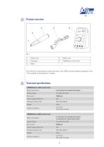
You will find a comprehensive system overview in the JOKE surface treatment catalogue, in the "Drive systems and handpieces" chapter. Technical specifications ENESKAmicro 450 control unit
Open the catalog to page 5
Safety Intended use ENESKAmicro systems are designed exclusively for grinding, milling, deburring and polishing with the tools listed and approved in the JOKE catalogue. ENESKAmicro systems may only be used with approved components and accessories (see chapter 3, Technical specifications). The values specified in the technical specifications of the individual components must not be exceeded when working with the ENESKAmicro system. ENESKAmicro control units may only be used as described in these operating instructions. Any other use or use going beyond this is considered improper use. The manufacturer...
Open the catalog to page 8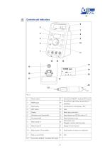
Power switch Connection B (BLDC - brushless DC motor) Connection C (DC carbon brush motor; if available) FOOT button Connection for a foot pedal or PLC LEFT button Mains plug connection Handpiece rest (if available) Speed display as ACTUAL value or % Carrying handle Information area: Plugged-in motors and foot pedal Display of timer function Motor button C (if available) On/off switch on motor (or handpiece) Rotary control knob Connection A (BLDC - brushless DC motor)
Open the catalog to page 9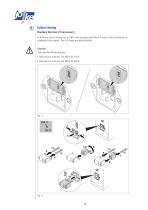
Initial startup Replace the fuse (if necessary) The control unit is factory set to 230 V and equipped with two 2 A fuses. One of these two is intended to be a spare. Two 4 A fuses are also included. Caution! Only use the following fuses: • Microfuse 5 x 20 mm, T4L 250 V for 115 V
Open the catalog to page 10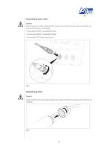
Connecting a motor cable Caution! Always insert the cable carefully into the socket on the control unit and make sure that the contacts and threads are not damaged. • Connection A: BLDC - brushless DC motor • Connection B: BLDC - brushless DC motor • Connection C: DC carbon brush motor MEM Connecting a motor Caution! Always connect motor and cable carefully and make sure that the contacts and threads are not damaged.
Open the catalog to page 11
Connecting a handpiece Caution! Carefully push the motor and the handpiece together and make sure that the contacts, the motor shaft, the handpiece coupling and the threads are not damaged. Always use the supplied tool. If there is resistance before the thread is completely screwed in, first turn the handpiece’s collet chuck manually until the coupling engages. Connecting the mains cable 2. 1.
Open the catalog to page 12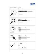
Setting the language (if necessary) Action Call up the main menu Select language menu Deutsch English Francais Cesky Espania Select language Deutsch English Francais Cesky Espania Save language Back to the start page
Open the catalog to page 13
Installing or changing a tool Warning! To avoid injuries caused by the tool turning unintentionally, only connect or change tools when the control unit is switched off. Warning! To avoid injuries caused by tools coming loose, always insert the tools into the collet chuck as far as they will go and also adjust the collet chuck on the JEHR 500, JIH 300 and JIR 310 handpieces. Caution! Thoroughly clean all parts before installing them. If it should be necessary to change the collet chuck: see chapter 13, "Changing the collet chuck".
Open the catalog to page 14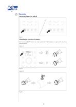
Operation Switching the unit on and off MEM Choosing the direction of rotation Anti-clockwise (LEFT) rotation can only be selected if the handpiece is approved for two directions of rotation. Option A:
Open the catalog to page 18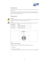
Choosing a motor Several motors can be connected to the control unit at the same time, but only one motor can be used at a time . The motor that was last connected to or was used with the control unit will automatically be selected . The motor button A, B or C belonging to this motor will flash . If necessary, press motor button A, B or C to select another motor. Setting the speed Warning! To avoid injury and damage to components due to excessive speeds, never exceed the maximum permissible speed of the connected components and accessories . Caution! To avoid damage to the handpiece, reduce the...
Open the catalog to page 19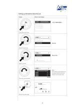
Calling up information about the unit Action Call up the main menu + __________ Select unit info. View the unit information Back to the start page Note: Information on operating hours, overload, faults and channel memory can be found here.
Open the catalog to page 21
Using foot mode A foot pedal can be used to control the speed of the tool using your foot during operation. Variable speeds between 0 and the set speed can be selected. Switching foot mode on A
Open the catalog to page 22
Using the memory function (MEM) The memory function makes it possible to store one speed, one direction of rotation (anticlockwise or clockwise) and the activated foot operation for each of the three connections (A, B or C) so that the settings are retained even if the control unit is switched off and then on again. If the memory function is activated (MEM button illuminated), the settings on the control unit cannot be changed. Saving settings Activating/deactivating settings
Open the catalog to page 23All Joke Technology catalogs and technical brochures
 ENESKAmarker 300
4 Pages
 ENESKAmobile
4 Pages
 ENESKArobotics
4 Pages
 ENESKAsonic
4 Pages
 ENESKApostpro
4 Pages
 ENESKAmicro
16 Pages
 Blasting systems
14 Pages
 Polishing and lapping technology
40 Pages
 Workplace systems
74 Pages
 Cleaning systems
18 Pages
 Grinding and polishing tools
216 Pages
 Chipping tools
40 Pages
 Diamond and boron nitride tools
62 Pages
 joke catalogue
451 Pages
 Laser welding
8 Pages
 FS katalog
72 Pages
 Welding and coating systems
46 Pages
 Sealing presses
8 Pages
 Film sealing devices
38 Pages


Archived catalogs
 2019 Repair welding
88 Pages
 Driving motors and handpieces
94 Pages
- Electromotor
- Milling tool
- Synchronous motor
- Welding system
- Solid milling cutter
- Marking machine
- EC motor
- Drilling tool
- Milling tool with replaceable insert
- Cylindrical cap
- Compact electromotor
- Laser marking machine
- 380 V motor
- Surface treatment brush
- Metal welding machine
- Ball nose milling cutter
- Metal marking machine
- Multi-purpose drilling tool
- Polishing unit