- Catalogs
- Johnson Electric
- Standard Linear Stepper Motors
Standard Linear Stepper Motors
1 /17Pages

Standard Linear Stepper Motors
1 /17Pages
Catalog excerpts
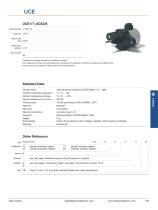
UCE UCE1/7; UCE2/8 Dimensions (mm) ∅ 28 x 31 Travel (mm) 10/13 Travel per step (mm) 0.021 Speed (mm/s) at 200 Hz 4.16 Max. Force (N)* 35 *Depends on winding, frequency and lifetime required. Drive against end stops only permissible after clarification of operating conditions and approval by Saia Motors. Radial forces on the shaft will reduce life time and performance. Standard Data Climatic class wide-spread according to DIN IEC 60721-2-1 : 1992 Ambient temperature operation °C -15 ... +60 Ambient temperature storage °C -20 ... +100 Thermal resistance at f=0 Rtherm 29 K/W Thermal class 130 (B) according to DIN EN 60085 : 2004 Approval standard Mounting any position Electrical connection connector type C, D Protection IP40 according to DIN EN 60529 : 2000 Weight 67 g Rotor stalling motor can be stopped when voltage is applied, without being overheated Bearings ball bearing Order Reference Type Stepper Motor bipolar, standard magnet unipolar, standard magnet see next pages “Connection Types” and page 145 “Connection Types” for B see next page, Resistance per winding for bipolar or unipolar Travel 13 mm ± 0.7 mm (other standard shafts see under dimensions) Saia motors bipolar, stronger magnet unipolar, stronger magnet
Open the catalog to page 1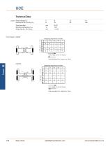
Technical Data bipolar Rated voltage UN: V 6 12 24 Winding temperature Tmax °C 130 Axial play at ± 20 N force mm < 0.25 Circuit diagram bipolar stepping sequence number Push out (step IV to I, step IV to I, etc.)
Open the catalog to page 2
UCE Dimensions: Version with connector D, 13mm travel, shaft 1B and 1E counter-connector Molex C-Grid lll 90142-0006 inner position outer position shaft 1B= cost effective solutions for forces up to 25N 3 19,1 Version with Connector D, with 50..150 mm travel, shaft 1R, 1S, 1Q counter connector Molex C-Grid III 90142-0006 Saia motors
Open the catalog to page 3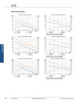
UCE Performance Chart UCE1 - Pull-in range constant voltage UCE1 - Pull-in range chopper (24 Ohms) P - ED 100 % F - ED 100 % P - ED 30 % F - ED 30 % 100% duty cycle: max. current per phase 180mA 30% duty cycle: max. current per phase 300mA UCE5 - Pull-in range constant voltage UCE5 - Pull-in range chopper (24 Ohms) 100% duty cycle: max. current per phase 180mA 30% duty cycle: max. current per phase 300mA UCE7 - Pull-in range constant voltage UCE7 - Pull-in range chopper (24 Ohms) 100% duty cycle: max. current per phase 180mA 30% duty cycle: max. current per phase 300mA Saia motors
Open the catalog to page 4
UCE Performance Chart UCE2 - Pull-in range constant voltage 40.0 F/N 35.0 UCE6 - Pull-in range constant voltage 50.0 F/N 45.0 UCE8 - Pull-in range constant voltage 60.0 F/N Saia motors
Open the catalog to page 5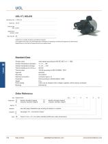
UCL UCL1/7; UCL2/8 Dimensions (mm) ∅ 28 x 31 Travel (mm) 10/13 Travel per step (mm) 0.041 Speed (mm/s) at 200 Hz 8.33 Max. Force (N)* 35 *Depends on winding, frequency and lifetime required. Drive against end stops only permissible after clarification of operating conditions and approval by Saia Motors. Radial forces on the shaft will reduce life time and performance. Standard Data Climatic class wide-spread according to DIN IEC 60721-2-1 : 1992 Ambient temperature operation °C -15 ... +60 Ambient temperature storage °C -20 ... +100 Thermal resistance at f=0 Rtherm 29 K/W Thermal class 130 (B)...
Open the catalog to page 6
bipolar Rated voltage UN: V Duty cycle % Resistance R20 Ω code Winding unipolar Rated voltage UN: V Duty cycle % Resistance R20 Ω code Winding step Travel per mm Winding temperature Tmax °C Axial play at ± 20 N force mm Circuit diagram bipolar p i n stepping sequence number I II III IV I Push out (step IV to I, step IV to I, etc.) stepping sequence number I II III IV I p i n n u m b e r Pull in (step I to IV, I to IV, etc.) Push out (step IV to I, step IV to I, etc.) Saia motors
Open the catalog to page 7
UCL Dimensions: Version with connector D, 13mm travel, shaft 1B and 1E Dimensions Version with Connector D, with 13 mm travel, shaft 1B and 1E counter-connector Molex C-Grid lll 90142-0006 inner position outer position shaft 1B= cost effective solutions for forces up to 25N 3 Version with Connector D, with 50..150 mm travel, shaft 1R, 1S, 1Q counter connector Molex C-Grid III 90142-0006 Saia motors
Open the catalog to page 8
UCL Performance Chart UCL1 - Pull-in range constant voltage UCL1 - Pull-in range chopper (24 Ohms) F - ED 100 % P - ED 100 % F - ED 30 % P - ED 30 % 100% duty cycle: max. current per phase 180mA 30% duty cycle: max. current per phase 300mA UCL5 - Pull-in range chopper (24 Ohms) UCL5 - Pull-in range constant voltage 0.80 P/ W 0.70 100% duty cycle: max. current per phase 180mA 30% duty cycle: max. current per phase 300mA UCL7 - Pull-in range constant voltage UCL7 - Pull-in range chopper (24 Ohms) 100% duty cycle: max. current per phase 180mA 30% duty cycle: max. current per phase 300mA Saia motors...
Open the catalog to page 9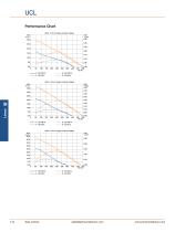
UCL Performance Chart UCL2 - Pull-in range constant voltage UCL6 - Pull-in range constant voltage 40.0 F/N 35.0 UCL8 - Pull-in range constant voltage 50.0 F/N 45.0 Saia motors
Open the catalog to page 10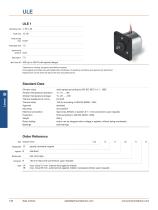
ULE ULE 1 Dimensions (mm) ∅ 55 x 55 Travel (mm) 10, 95 Travel per step (mm) 0.031 Thread pitch (mm) 1.5 Speed (mm/s) at 200 Hz 6.25 Step angle (°) 7.5 Max. Force (N)* 400 (up to 400 N with special design) *Depends on winding, frequency and lifetime required. Drive against end stops only permissible after clarification of operating conditions and approval by Saia Motor. Radial forces on the shaft will reduce life time and performance. Standard Data Climatic class wide-spread according to DIN IEC 60721-2-1 : 1992 Ambient temperature operation °C -15 ... +60 Ambient temperature storage °C -20 ......
Open the catalog to page 11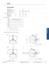
Technical Data Winding temperature Tmax Axial play at ± 50 N force bipolar Rated voltage UN V Duty cycle % Winding code Circuit diagram bipolar mm 95 (others upon request) Push out (step IV to I, step IV to I, etc.) Dimensions Version with lead wires, 10 mm travel dimensions without tolerance are iust for information Saia motors
Open the catalog to page 12
ULE Performance Chart ULE1 - Pull-in range constant voltage 350.0 F/ N ULE1 - Pull-in range chopper at 24V (5.1 Ohms) ULE1 - Pull-out range chopper at 24V vs. 48V (5.1 Ohms) 1.60 P/ W 100% duty cycle: max. current per phase 825mA with holding current of 275mA 100% duty cycle: max. current per phase 825mA with holding current of 275mA 30% duty cycle: max. current per phase 1500mA with holding current of 500mA 30% duty cycle: max. current per phase 1500mA with holding current of 500mA Saia motors
Open the catalog to page 13All Johnson Electric catalogs and technical brochures
 BTA® Size 6EV
2 Pages
 VersaSortTM Modules
2 Pages
 Ledex® Rotary Solenoids
2 Pages
 TrueDrive™ Motorized Rollers
4 Pages
 Solligence™ Actuators
3 Pages
 Solutions by industry
26 Pages
 Automotive Products Group
10 Pages
 Industry Products Group
11 Pages
 SMART METERING
14 Pages
 Ultimag® Rotary Actuators
3 Pages
 Ledex® Tubular Solenoids
37 Pages
 Soft Shift® Solenoids
3 Pages
 Low Profile Solenoids
3 Pages
 Nanomotion Motion Systems
9 Pages
 Compact Lite Window Lift Drive
12 Pages
 Nanomotion-Motors
8 Pages
 Compact AC Starters
4 Pages
 Shaded Pole Motors
32 Pages
 Saia Motors
157 Pages
 Secure Flex
1 Page
 Prepayment Meter Valves
2 Pages
 Smart Meter Valves
2 Pages
 Diverter Valve
13 Pages
 Drive Electronics
3 Pages
 Standard Rotary Stepper Motors
38 Pages
 Rotary Synchronous Motors
91 Pages
 Universal AC Motors
48 Pages
 vd751(0)-101
2 Pages
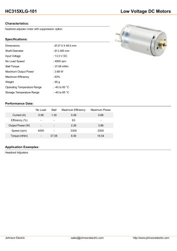 hc315xlg-101
2 Pages
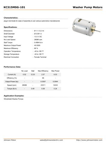 kc315msg-101
2 Pages
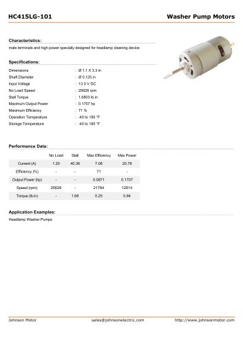 HC415LG-101
2 Pages
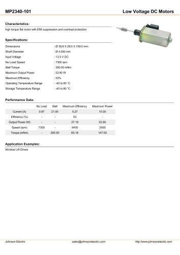 mp2340-101
2 Pages
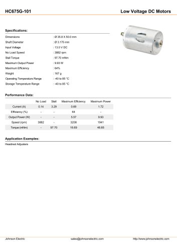 hc675g-101
2 Pages
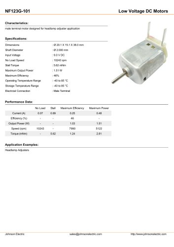 NF123g-101
2 Pages
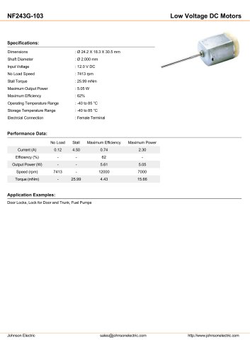 nf243g-103
2 Pages
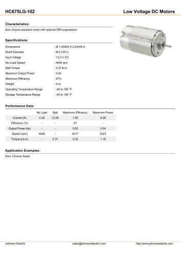 hc675lg-102
2 Pages
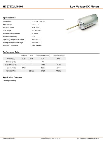 HC675XLLG-101
2 Pages


Archived catalogs
 hc658ulg-101
2 Pages
 mo25wj-101
2 Pages
 hF658ulg-105
2 Pages
 mo25mm-102
2 Pages
 Specialized switching solution
24 Pages
 TH-contact panel mounted push button
112 Pages
 Burgess Switches
80 Pages
 saia microswitches
54 Pages
 Saia-Motors
218 Pages
 Johnsonelectric brochure
22 Pages
 LEDEX DC Solenoids Metric
228 Pages
 LEDEX DC Solenoids Imperial
228 Pages
 Dormeyer AC Solenoids Imperial
52 Pages
 Johnson DC Motors
231 Pages
 Synchronous_Motors
2 Pages

- Actuator
- Electric actuator
- Industrial actuator
- DC actuator
- Rotary actuator
- High-speed actuator
- Maintenance-free actuator
- Motorized roller
- Servo-actuator
- Electric servo-actuator
- Conveyor drum motor
- High-torque actuator
- Rugged actuator
- Powerful actuator
- Rotary servo-actuator
- Precision servo-actuator
- DC servo-actuator
- Wheel block
- High-speed servo-actuator
- 24-volt servo-actuator