
Catalog excerpts

METAL MEMBRANE COUPLING L SERIES Technical Specification A – Stainless steel flexible membranes B – Overload and anti-fly protection collars A C – Anti-corrosion treatment D – Membrane unit assembly for ease of fitting E – Fitted bolts for balance integrity C F – Scalloped hubs to maximize bore Product Description John Crane’s Metastream L Series range of membrane couplings has been specifically designed to provide a cost-effective solution for demanding industrial applications. The couplings are selected by their torque capacity, with the scalloped hub providing the right size for the shaft. • Easy to install • Operates in either direction • A hubs supplied either finish machined or solid • Coated carbon steel hardware for corrosion protection • Choice of hub configuration to suit the shaft diameter • ATEX compliant Design Features • it and forget – Designed for infinite life and, with correct F machinery alignment, will often outlast the machines it connects • verload protection — Fitted with overload collars to protect O the membranes in the event of severe torsional overload • ow imposed loads — Designed to optimize torque capability L while minimizing reaction forces due to misalignment, maximizing the life of the machines connected • Zero maintenance — Requires no lubrication or routine maintenance • o backlash — Torsionally stiff design ensures there is N zero backlash, making coupling ideal
Open the catalog to page 1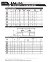
METAL MEMBRANE COUPLING L SERIES Technical Specification L Series Typical Arrangement D L Series Imperial Dimensional Data (Inches) Coupling Size Notes: 1 Maximum bores shown are based on standard ANSI/AGMA square key dimensions for sizes 0007 through 3000 and rectangular key dimensions for sizes 4200 through 9025. 2 Dimensions should not be used for construction. Certified dimensions furnished upon request. 3 X These distance between shaft end (DBSE) sizes are more readily available. Other lengths to suit specific shaft separations are available.
Open the catalog to page 2
METAL MEMBRANE COUPLING L SERIES Technical Specification L Series Typical Arrangement D Notes: 1 Maximum bores shown are based on standard DIN/BS rectangular keys. 2 Dimensions should not be used for construction. Certified dimensions furnished upon request. 3 X These distance between shaft end (DBSE) sizes are more readily available. Other lengths to suit specific shaft separations are available.
Open the catalog to page 3
METAL MEMBRANE COUPLING L SERIES Technical Specification Selection Procedure (Metric) 1. Select appropriate service factor (SF) 2. Calculate the coupling rating R from: R = kW x 1000 x SF (kW/1,000 rpm) N Where: kW = rated power for driven equipment (kW) N = speed (rpm) 3. Select a coupling with the same or higher rating. 4. Check distance between shaft ends (DBSE). 5. Check the hub bore capacity is suitable. If not, select a larger size coupling. 6. Check peak torque capability is suitable for application. 7. Check speed capability is suitable. 8. Specify DBSE as appropriate. Selection...
Open the catalog to page 4
METAL MEMBRANE COUPLING L SERIES Technical Specification Coupling Alignment Correct installation and alignment of shafts are essential for reliable machinery performance. The angular and axial restoring forces in the table below are given at maximum deflections. The chart can be used to determine forces across the full deflection range. The nonlinear characteristics of axial stiffness can dampen a system to prevent high-amplitude axial vibration. Restoring Max. (2) Moment (3) Axial Equivalent Max. at Max. Max. ± mm Coupling Equivalent Thrust Angular Angle Parallel kN Degrees Nm mm Size...
Open the catalog to page 5
METAL MEMBRANE COUPLING L SERIES Technical Specification
Open the catalog to page 6
METAL MEMBRANE COUPLING L SERIES Technical Specification
Open the catalog to page 7
METAL MEMBRANE COUPLING L SERIES Technical Specification North America United States of America Europe United Kingdom Latin America Brazil Middle East & Africa United Arab Emirates Asia Pacific Singapore If the products featured will be used in a potentially dangerous and/or hazardous process, your John Crane representative should be consulted prior to their selection and use. In the interest of continuous development, John Crane Companies reserve the right to alter designs and specifications without prior notice. It is dangerous to smoke while handling products made from PTFE. Old and new...
Open the catalog to page 8All John Crane catalogs and technical brochures
-
 John Crane Couplings
4 Pages
-
 Type 28VL
4 Pages
-
 Type 93FR
4 Pages
-
 TYPE 8648VRS
2 Pages
-
 AURA™
AURA™2 Pages
-
 SEAL FACE TECHNOLOGIES
2 Pages
-
 H-RE
H-RE12 Pages
-
 H-CE
H-CE12 Pages
-
 CPKT
CPKT1 Pages
-
 A series
8 Pages
-
 TYPE 3604/3604HTC/3604HTCDP
8 Pages
-
 TYPE 2800MB
8 Pages
-
 TYPE 2715T
8 Pages
-
 2609HTC/3609HTC
8 Pages
-
 TYPE 1670
4 Pages
-
 G58/G58I
2 Pages
-
 CVU/CVH
2 Pages
-
 CRANE-FOIL™
2 Pages
-
 PACKING SOLUTIONS
2 Pages
-
 CPR BUSHING
4 Pages
-
 TYPE EZ-1®
8 Pages
-
 GR-2/2C
2 Pages
-
 GR-1/1C
2 Pages
-
 LIVE-LOAD
2 Pages
-
 1345/1349
2 Pages
-
 387I
387I2 Pages
-
 Type 5611/5611Q
8 Pages
-
 TYPE 502
6 Pages
-
 TYPE 2106
4 Pages
-
 AURA™ 180/220
4 Pages
-
 TYPE 676
8 Pages
-
 CLEARANCE SEALS
8 Pages
-
 TYPE 2100
4 Pages
-
 TYPE 21
6 Pages
-
 TYPE 1/1B
6 Pages
-
 Filter Elements
8 Pages
-
 Combined Bearings
8 Pages
-
 GR2/2C
2 Pages
-
 GR1/1C
2 Pages
-
 GP-S/GP-D
2 Pages
-
 Cyclone Separators
4 Pages
-
 Air-Cooled Heat Exchanger
2 Pages
-
 682 Reservoir
2 Pages
-
 Type 93FR
4 Pages
-
 Type 83
4 Pages
-
 Type 28XP
6 Pages
-
 Type 28VL
4 Pages
-
 Type 28ST
4 Pages
-
 CK736/736D
4 Pages
-
 SE2 ScrewPumps
4 Pages
-
 SEW Ahlstar
4 Pages
-
 Mechanical Packing
12 Pages
-
 Tilting Pad Bearings
20 Pages
-
 Engineered Coupling Solutions
12 Pages
-
 Fuel Gas Filtration
8 Pages


Archived catalogs
-
 Type 28AT_2015
8 Pages
-
 Type 28AT_2012
6 Pages
-
 Engineered Coupling Solutions
12 Pages
-
 Water-Cooled Heat Exchanger
12 Pages
-
 Type 2800 Control Panel
12 Pages
-
 682 Reservoir
12 Pages

