
Catalog excerpts

H SERIES COPLANAR COUPLINGS Fitting & Maintenance General Specification John Crane’s Metastream torsionally rigid H-CE flexible coupling is a high-performance, dynamically balanced, low-moment coupling typically for use on high-speed mechanical drives (turbines, pumps, compressors). Additionally, due to interlocking flanges, it is designed to cater for large overload torques and maintain the drive until the machinery can be safely brought to rest in the event of failure of the flexing elements. A general arrangement (GA) drawing is always supplied for high-performance couplings. These instructions are to be read in conjunction with the GA and any specific information on the drawing takes precedence over the general information included herein. NOTE: Throughout these instructions, the generic high-performance coupling code H-CE indicates HSCE and HLCE. Extent of Supply The coupling will generally be supplied in the following configuration: • Factory-assembled coupling complete with hub-mounted membrane assemblies and spacer piece. The whole coupling will have been dynamically balanced for high-speed applications. • The hub/membrane units are delivered fitted with gagging bolts, painted red and blue, to give protection during transportation and to aid installation of the coupling. These must be removed before running the coupling. • If requested, the coupling can be supplied with a number of packing shims to allow the coupling length to be adjusted on site to suit the specific application. Refer to the specific GA drawing for details of the use of these shims. Selection Verification Although a coupling may be correctly specified at the time of order placement, the duty conditions can sometimes change prior to the coupling being put into service. Information is available from John Crane to advise on the selection and limitations of their power transmission products, but the user is ultimately responsible for verifying the suitability of the selection for the actual service conditions. The coupling and its manner of use must conform to any legal or licensing requirements and, where appropriate, meet local health and safety requirements. IMPORTANT If the conditions of operation are changed without approval from John Crane, then we would decline responsibility for any consequent damage and the user would assume all risks. Handling and Storage • Couplings and components should be stored in a dry building away from direct heat. • For maximum protection, the coupling and components should be stored in the original packaging. If any packaging has been removed or damaged in transit, it should be restored to a secure safely packaged condition. • The coupling should be stored horizontally and should not be stood on end for long periods. Avoid shock during handling and protect against corrosion. • Always examine parts thoroughly when taking them from storage for signs of damage or deterioration. • During transport, handling and storage, the gagging bolts (painted red and blue for identification) should be in position. • Following installation of the coupling, all transit gags and bolts should be tagged with the plant/coupling ID and stored ready for subsequent reuse on coupling removal, as should ancillary items, such as spare shims. • Documentation supplied with the coupling should be retained fo
Open the catalog to page 1
H SERIES COPLANAR COUPLINGS Fitting & Maintenance Installation of Coupling • Refer to the assembly drawing for all dimensions. • Inspect the coupling to ensure that it is undamaged and note any match marks that must be aligned when the coupling is installed. • Set the distance between the shaft ends (DBSE), taking into account any axial movements and thermal expansion which may occur in operation. The final operating distance must be as close as possible to that shown on the arrangement drawing. The shafts should then be aligned. • Separate the individual hub/membrane units from the spacer....
Open the catalog to page 2
H SERIES COPLANAR COUPLINGS Fitting & Maintenance Installation of Coupling (continued) Fit and secure the axial ram or hydraulic nut BEFORE injecting oil between the components. 9. Inject oil between the component interface until the required mounting pressure is reached or it leaks out at the ends of the mating surfaces. 10. By means of the mounting tools, draw the hub up the shaft to the correct axial position, injecting oil during this operation. NOTE: The correct pull-up distance should be shown on the GA drawing along with max. permissible installation pressure. 11. Release the...
Open the catalog to page 3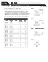
Membrane unit compression for the coplanar coupling Before the spacer can be fitted between the membrane units, it is necessary to compress the membranes. The following instructions detail each membrane unit compression: 1. Remove the red-painted socket-headed bolts from the guard ring flange of the membrane unit (i.e., three bolts for the HSCE and four bolts for the HLCE [see Figures 3A and 3D]). 2. Tighten the blue-painted socket-headed bolts. Refer to Table 1 for the number of tightening turns. NOTE: Please rnlts are tightened in stages to ensure even loading (Figure 3B] Figure 3C shows...
Open the catalog to page 4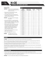
H SERIES COPLANAR COUPLINGS Fitting & Maintenance Fitting the spacer IMPORTANT The spacer must be supported throughout this step to ensure that the weight is never imposed on one end only. • Bring the spacer into position between the flanges, taking care to align any match marks. • Fit the stripper bolts (4) and nuts (6) loosely to hold the spacer. Remove the gagging screws and store these safely with the sleeves for future use. IMPORTANT Do olts with gagging bolts installed. • Bolts should be tightened in a "diametrically opposite" sequence to the torque values quoted in Table 2. Always...
Open the catalog to page 5
H SERIES COPLANAR COUPLINGS Fitting & Maintenance Gagging method for the coplanar coupling The gagging method for the HSCE and HLCE coplanar couplings employs a push-pull bolt arrangement. The red-painted socket-headed bolt is the push, or stop bolt. Three bolts per membrane unit are required for the HSCE. Four bolts per membrane unit are required for the HLCE. The blue-painted socket-headed bolt is the puller bolt. Three bolts per membrane unit are required for the HSCE. Four bolts per membrane unit are required for the HLCE. The following instructions detail the gagging of each membrane...
Open the catalog to page 6All John Crane catalogs and technical brochures
-
 John Crane Couplings
4 Pages
-
 L SERIES
8 Pages
-
 Type 28VL
4 Pages
-
 Type 93FR
4 Pages
-
 TYPE 8648VRS
2 Pages
-
 AURA™
AURA™2 Pages
-
 SEAL FACE TECHNOLOGIES
2 Pages
-
 H-RE
H-RE12 Pages
-
 CPKT
CPKT1 Pages
-
 A series
8 Pages
-
 TYPE 3604/3604HTC/3604HTCDP
8 Pages
-
 TYPE 2800MB
8 Pages
-
 TYPE 2715T
8 Pages
-
 2609HTC/3609HTC
8 Pages
-
 TYPE 1670
4 Pages
-
 G58/G58I
2 Pages
-
 CVU/CVH
2 Pages
-
 CRANE-FOIL™
2 Pages
-
 PACKING SOLUTIONS
2 Pages
-
 CPR BUSHING
4 Pages
-
 TYPE EZ-1®
8 Pages
-
 GR-2/2C
2 Pages
-
 GR-1/1C
2 Pages
-
 LIVE-LOAD
2 Pages
-
 1345/1349
2 Pages
-
 387I
387I2 Pages
-
 Type 5611/5611Q
8 Pages
-
 TYPE 502
6 Pages
-
 TYPE 2106
4 Pages
-
 AURA™ 180/220
4 Pages
-
 TYPE 676
8 Pages
-
 CLEARANCE SEALS
8 Pages
-
 TYPE 2100
4 Pages
-
 TYPE 21
6 Pages
-
 TYPE 1/1B
6 Pages
-
 Filter Elements
8 Pages
-
 Combined Bearings
8 Pages
-
 GR2/2C
2 Pages
-
 GR1/1C
2 Pages
-
 GP-S/GP-D
2 Pages
-
 Cyclone Separators
4 Pages
-
 Air-Cooled Heat Exchanger
2 Pages
-
 682 Reservoir
2 Pages
-
 Type 93FR
4 Pages
-
 Type 83
4 Pages
-
 Type 28XP
6 Pages
-
 Type 28VL
4 Pages
-
 Type 28ST
4 Pages
-
 CK736/736D
4 Pages
-
 SE2 ScrewPumps
4 Pages
-
 SEW Ahlstar
4 Pages
-
 Mechanical Packing
12 Pages
-
 Tilting Pad Bearings
20 Pages
-
 Engineered Coupling Solutions
12 Pages
-
 Fuel Gas Filtration
8 Pages


Archived catalogs
-
 Type 28AT_2015
8 Pages
-
 Type 28AT_2012
6 Pages
-
 Engineered Coupling Solutions
12 Pages
-
 Water-Cooled Heat Exchanger
12 Pages
-
 Type 2800 Control Panel
12 Pages
-
 682 Reservoir
12 Pages

