
Catalog excerpts
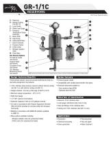
GR-1/1C A – Reservoir C B – Internal Cooling Coil (GR-1C) A C – Level Switch D – Offset Level Gauge D E – Pressure/ Temperature Gauge Assembly E F – Name Plate G – Hand Pump H – Safety Relief Valve I – Quick Connector J – Pressure Switch K – Orifice Union L – Nitrogen Isolation Valve M – Drain Valve Non Stocked Options Fin Tube Air Cooler (not shown) Support Stand F (not shown) Circulation Pump (not shown) B 3in1 Wireless Monitoring Device (not shown) Technical Specification NOTE: Hand pump and pressure switch are panel mounted. Panel is not shown. Instrument mounting varies depending on the option selected. D e s ig n F e a tu re s/ Be ne fit s These general industry reservoirs provide buffer/barrier fluid to a dual seal arrangement. Key features: • 316/L stainless steel pressure reservoir without internal cooling coil (GR-1) or with internal cooling coil (GR-1C) • Design pressure: 16.3 bar g (236 psig), @100°C (212°F) • Minimum design temperature: -10°C (14°F) • Sight level gauge • 1/2" NPT reservoir terminations • Reservoir Capacity: 8 litre (2.2 US gallons) nominal • CE mark in accordance with Pressure Equipment Directive (PED) 97/23/CE provided to countries within the European Community • Welding in accordance with ASME VIII (welders qualified to ASME IX) • Many options available including: - Nitrogen isolation valve (for pressurized seals) - Orifice union (for unpressurized seals) Opti on Vari ants • Pressure gauge ranges • Compatibility with variable barrier/buffer fluid types • Electrical instruments suitable for: – Eexi circuits or Eexd (ATEX) – Explosion proof (UL/CSA) Materi als of Const ruct ion • Reservoir: 316/L stainless steel • Level gauge: aluminium body, buna O-ring • Tube and fittings: 316/L stainless steel • Cooling coil: 316/L stainless steel (GR-1C only) A ppl icati ons • Automotive • Chemical processing •
Open the catalog to page 1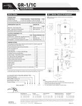
Technical Specification G R-1 S eries Typi cal A rrangem e n t PRESSURE RANGE Working Pressure Pressure Gauge Range Pressure Switch Range Code 0-6 bar g (0-100 psig) 0-10 bar g (0-150 psig) 0-6 bar g (0-100 psig) A 6-16.3 bar g (100-236 psig) max 0-25 bar g (0-360 psig) 6-20 bar g (100-300 psig) B NOTE: Instrument mounting is indicative only and may vary depending on the options selected 169 Ø [6 5/8"] COOLING COIL ELECTRICAL ENVIRONMENT TYPE Electrical Protection Code Electrical Certification Code Explosion Proof – switches Eexd, circulating pump Eexe F UL/CSA U Eexi – for intrinsically...
Open the catalog to page 2All John Crane catalogs and technical brochures
-
 John Crane Couplings
4 Pages
-
 L SERIES
8 Pages
-
 Type 28VL
4 Pages
-
 Type 93FR
4 Pages
-
 TYPE 8648VRS
2 Pages
-
 AURA™
AURA™2 Pages
-
 SEAL FACE TECHNOLOGIES
2 Pages
-
 H-RE
H-RE12 Pages
-
 H-CE
H-CE12 Pages
-
 CPKT
CPKT1 Pages
-
 A series
8 Pages
-
 TYPE 3604/3604HTC/3604HTCDP
8 Pages
-
 TYPE 2800MB
8 Pages
-
 TYPE 2715T
8 Pages
-
 2609HTC/3609HTC
8 Pages
-
 TYPE 1670
4 Pages
-
 G58/G58I
2 Pages
-
 CVU/CVH
2 Pages
-
 CRANE-FOIL™
2 Pages
-
 PACKING SOLUTIONS
2 Pages
-
 CPR BUSHING
4 Pages
-
 TYPE EZ-1®
8 Pages
-
 GR-2/2C
2 Pages
-
 LIVE-LOAD
2 Pages
-
 1345/1349
2 Pages
-
 387I
387I2 Pages
-
 Type 5611/5611Q
8 Pages
-
 TYPE 502
6 Pages
-
 TYPE 2106
4 Pages
-
 AURA™ 180/220
4 Pages
-
 TYPE 676
8 Pages
-
 CLEARANCE SEALS
8 Pages
-
 TYPE 2100
4 Pages
-
 TYPE 21
6 Pages
-
 TYPE 1/1B
6 Pages
-
 Filter Elements
8 Pages
-
 Combined Bearings
8 Pages
-
 GR2/2C
2 Pages
-
 GR1/1C
2 Pages
-
 GP-S/GP-D
2 Pages
-
 Cyclone Separators
4 Pages
-
 Air-Cooled Heat Exchanger
2 Pages
-
 682 Reservoir
2 Pages
-
 Type 93FR
4 Pages
-
 Type 83
4 Pages
-
 Type 28XP
6 Pages
-
 Type 28VL
4 Pages
-
 Type 28ST
4 Pages
-
 CK736/736D
4 Pages
-
 SE2 ScrewPumps
4 Pages
-
 SEW Ahlstar
4 Pages
-
 Mechanical Packing
12 Pages
-
 Tilting Pad Bearings
20 Pages
-
 Engineered Coupling Solutions
12 Pages
-
 Fuel Gas Filtration
8 Pages


Archived catalogs
-
 Type 28AT_2015
8 Pages
-
 Type 28AT_2012
6 Pages
-
 Engineered Coupling Solutions
12 Pages
-
 Water-Cooled Heat Exchanger
12 Pages
-
 Type 2800 Control Panel
12 Pages
-
 682 Reservoir
12 Pages

