
Catalog excerpts

MODEL 10/20/30 Cyclone Separators These cyclone separators utilize a one-piece pressure casing, eliminating temperature and pressure constraints imposed by designs using bolted and gasketed casing covers. The simple construction reduces the maintenance and inventory costs associated with more complex designs. The efficient, lightweight assembly provides lower pipe stress when inline mounted, while offering operating pressures up to 207 bar/3000 psi. One-Piece Pressure Casing. Tungsten Carbide (Model 10), Stellite (Model 20), and Stellite/Stainless Steel (Model 30) Inserts. NPT, Socket Weld, Butt Weld, or Military O-Ring Connection Chemical Processing Food Processing Metal Finishing Municipal Pipeline Pharmaceutical Power Generation Pulp and Paper Refinery Water Treatment ASTM A744 GRD CF8M: ASTM A 494 GRD M35-1: ASTM A 890 GRD 1A: ASTM A 890 GRD 4A: ASTM A 494 GRD CW12MW: 316SS Monel® 400 25-5 Duplex 2205 Duplex Hastelloy C Monel is a registered trademark of Inco Alloys International, Inc.
Open the catalog to page 1
Cyclone Separators Dimensional Data (mm) I Dimensional Data (inches) *N0TE: Model 30 is manufactured with E dimension located to the opposite side as shown.
Open the catalog to page 2
MODEL 10/20/30 Cyclone Separators Technical Data There are several operational factors that will adversely affect the expected performance of your cyclone separator. ■ Abrasive Particle Size and Specific Gravity A cyclone separator’s removal efficiency increases as the particle size increases and as the differential between the liquid and particle’s specific gravity increases. The practical lower limit of particle sizes for effective separation is 1 micron. The particle’s specific gravity must always be greater than the fluid’s. Solids Content The solids content of the pumped fluid should...
Open the catalog to page 3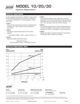
MODEL 10/20/30 Cyclone Separators Selection Requirements Cyclone separator performance is affected by many factors, but the following procedure will normally be satisfactory for selection requirements. For further guidance, consult John Crane. ■ STEP 2 Establish the required total capacity of the cyclone separator. Total Capacity (GPM or LPM) = Clean Flow Rate x 1.4 STEP 5 If the selected separator gives a flow rate greater than the maximum acceptable, a flow controller should be fitted at position A as shown in the diagram on the previous page. STEP 1 Determine the maximum and minimum...
Open the catalog to page 4All John Crane catalogs and technical brochures
-
 John Crane Couplings
4 Pages
-
 L SERIES
8 Pages
-
 Type 28VL
4 Pages
-
 Type 93FR
4 Pages
-
 TYPE 8648VRS
2 Pages
-
 AURA™
AURA™2 Pages
-
 SEAL FACE TECHNOLOGIES
2 Pages
-
 H-RE
H-RE12 Pages
-
 H-CE
H-CE12 Pages
-
 CPKT
CPKT1 Pages
-
 A series
8 Pages
-
 TYPE 3604/3604HTC/3604HTCDP
8 Pages
-
 TYPE 2800MB
8 Pages
-
 TYPE 2715T
8 Pages
-
 2609HTC/3609HTC
8 Pages
-
 TYPE 1670
4 Pages
-
 G58/G58I
2 Pages
-
 CVU/CVH
2 Pages
-
 CRANE-FOIL™
2 Pages
-
 PACKING SOLUTIONS
2 Pages
-
 CPR BUSHING
4 Pages
-
 TYPE EZ-1®
8 Pages
-
 GR-2/2C
2 Pages
-
 GR-1/1C
2 Pages
-
 LIVE-LOAD
2 Pages
-
 1345/1349
2 Pages
-
 387I
387I2 Pages
-
 Type 5611/5611Q
8 Pages
-
 TYPE 502
6 Pages
-
 TYPE 2106
4 Pages
-
 AURA™ 180/220
4 Pages
-
 TYPE 676
8 Pages
-
 CLEARANCE SEALS
8 Pages
-
 TYPE 2100
4 Pages
-
 TYPE 21
6 Pages
-
 TYPE 1/1B
6 Pages
-
 Filter Elements
8 Pages
-
 Combined Bearings
8 Pages
-
 GR2/2C
2 Pages
-
 GR1/1C
2 Pages
-
 GP-S/GP-D
2 Pages
-
 Air-Cooled Heat Exchanger
2 Pages
-
 682 Reservoir
2 Pages
-
 Type 93FR
4 Pages
-
 Type 83
4 Pages
-
 Type 28XP
6 Pages
-
 Type 28VL
4 Pages
-
 Type 28ST
4 Pages
-
 CK736/736D
4 Pages
-
 SE2 ScrewPumps
4 Pages
-
 SEW Ahlstar
4 Pages
-
 Mechanical Packing
12 Pages
-
 Tilting Pad Bearings
20 Pages
-
 Engineered Coupling Solutions
12 Pages
-
 Fuel Gas Filtration
8 Pages


Archived catalogs
-
 Type 28AT_2015
8 Pages
-
 Type 28AT_2012
6 Pages
-
 Engineered Coupling Solutions
12 Pages
-
 Water-Cooled Heat Exchanger
12 Pages
-
 Type 2800 Control Panel
12 Pages
-
 682 Reservoir
12 Pages

