
- Catalogs
- Johannes Hübner Giessen
- Bracket arms


Bracket arms

Bracket arms
Overview
This technical document from Johannes Hübner GmbH provides detailed guidance on the selection, mounting, and adjustment of torque bracket arms for hollow shaft incremental encoders of the FGH series (types 4, 6, 8, 14, 20). It focuses on ensuring high mounting precision to minimize measurement errors caused by shaft misalignments and mechanical tolerances.
1. Mounting Accuracy and Error Sources
The document identifies three main sources of mounting errors affecting the encoder's rotational accuracy:
- Radial eccentricity of the drive shaft (α1): The concentricity tolerance of the drive shaft or adapter shaft must be less than 0.04 mm (±0.02 mm). Adapter shafts can be adjusted using ball-thrust screws and aligned with a dial gauge.
- Radial eccentricity due to fitting tolerance (α2): Fits must comply with ISO 286/DIN 7145 standards. The encoder bore is H7, with recommended shaft fits of g6 for standard precision and h5 for higher precision. Shaft diameters should be manufactured slightly undersized (-0.005 to -0.015 mm) relative to the encoder bore for optimal fit.
- Axial motion of the drive shaft (α3): Axial shaft movements can cause angular errors, which are reduced by longer torque bracket lever arms. The total angular misalignment (αF = α1 + α2 + α3) must be significantly less than one quarter of the encoder's increment angle to avoid signal distortion.
2. Error Summation and Selection Criteria
The total misalignment angle αF is the sum of the three error components and represents the maximum rotational oscillation of the encoder housing. The document provides a selection table correlating pulse rate, increment angle, and lever arm length to allowable misalignment angles (αJ). The key requirement is:
αF < αJ (one quarter of the increment angle)
Users are instructed to:
- Determine αJ from the pulse rate using the provided diagram.
- Calculate αF based on measured or estimated shaft eccentricities and axial motion.
- Select the torque bracket lever arm length that ensures αF < αJ.
3. Torque Bracket Lever Arm Lengths and Dimensions
The document lists standard and special lever arm lengths (B and L) for different FGH encoder types and versions (insulated short, insulated long). Dimensions and drawings are referenced for each type, with options for custom lengths on request.
4. Mounting Instructions for Torque Bracket Link Heads
Key points include:
- High-performance link heads are maintenance-free but should be checked 1-2 times per year for free rotation and treated with Teflon spray or light oil.
- For harsh environments (open-cast mining, marine, corrosive), stainless steel link heads are recommended (extra cost).
- Link heads must not be contaminated with paint.
- Proper mounting ensures the link rod rotates freely without distortion to avoid excessive bearing loads and premature failure.
5. Accessories and Components
The document details accessories such as base plates, flange plates, spacer rings, self-locking nuts, and screws made from fiberglass-reinforced plastic for insulated torque brackets. Spacer rings are critical for maintaining the correct swivel range.
6. Mounting Examples and Best Practices
Examples illustrate the ideal mounting angle between the bracket arm and link rod (90°). Deviations reduce the effective lever arm length and increase angular errors. The document also references specialized tools like detaching devices and covers with gaskets for assembly and disassembly.
7. Detailed Assembly Components
Exploded views and parts lists are provided for insulated torque brackets of various diameters (Ø8, Ø12, Ø14), including screws, spacer rings, link rods with link heads, base plates, and locking nuts. Specific DIN standards for fasteners are cited.
Critical Information Summary
- Maintain drive shaft concentricity < 0.04 mm to minimize α1 error.
- Use recommended fits (H7 bore, g6 or h5 shaft) to control α2 error.
- Minimize axial shaft motion or compensate with longer lever arms to reduce α3 error.
- Sum of errors αF must be less than one quarter of the encoder increment angle (αJ) to ensure signal quality.
- Regular maintenance of link heads is essential for longevity.
- Use appropriate accessories and follow mounting instructions precisely.
This document is essential for engineers and technicians installing FGH hollow shaft encoders with torque brackets to achieve optimal measurement accuracy and mechanical reliability.
Catalog excerpts

Selection table of bracket arms Additional data sheet to hollow shaft encoder FGH 4-6-8-14-20 Johannes Hubner • Fabrik elektrischer Maschinen GmbH
Open the catalog to page 1
Anbaugenauigkeit von Hohlwellen-Impulsgeber Typenreihe FGH... in Abhängigkeit von: • Radialschlag der Antriebswelle • Radialschlag durch Passungsspiel • Axialbewegung der Antriebswelle Radial eccentricity of drive shaft – misalignment α 1 Requested concentricity tolerance of the drive shaft resp. of the mounted adapter flange must be less than 0.04 mm (± 0.02) which corresponds to the data of the assembly instructions (operating and Maintenance instructions). Adapter shafts are feasible with additonal ball-thrust screws for adjustment. Alignment is to be made by a dial gauge. II. Radial eccentricity...
Open the catalog to page 2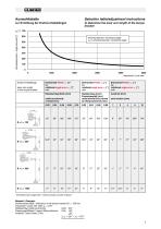
Selection table/adjustment instructions to determine the lever arm length of the torque bracket Winkelsekunden / angle seconds [″] Inkrementwinkel / increment angle αJ:1/4 Inkrementwinkel / increment angle 5000 Impulszahl / puls rate lever arm length of the torque bracket Drehwinkel-Fehler α 1 [″]* bei rotational angle error α 1 [ ″]* with Drehwinkel-Fehler α 2 [″] bei rotational angle error α 2 [ ″] with Drehwinkel-Fehler α 3 [″] bei rotational angle error α 3 [ ″] with Radialschlag durch Passungsspiel [mm] radial eccentricity caused by fitting tolerance [mm] radial eccentricity of shaft [mm]...
Open the catalog to page 3
Please specify lever arm length B and L /LH Isolierte* Drehmo kurz, direkt am Gehäuse angebaut Insulated* torque bracket short version effektive Hebellänge actual lever length * nicht isoliert bei FGH 14 – Ausführung „Mining“; bei FGH 6 nach Bestellung. * non-insulated for FGH 14 – for „mining“; for FGH 6 on request only. Zeichnung dimension drawing Isolierte Drehmo**, lange Version Insulated torque bracket**, long version Zeichnung dimension drawing Andere Abmessungen B + L auf Anfrage / other dimensions B + L on request
Open the catalog to page 4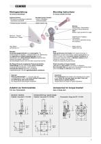
Mounting Instructions for torque bracket link head Isolierte Drehmo: • Schraube aus glasfaserverstärktem, hochfestem Kunststoff Insulated torque bracket: • screw of fibreglass reinforced plastic • plastic spacer ring Wichtig: Distanzringe / Stützscheibe – wichtig für Schwenkbereich Note: Spacer rings important for angle Stützarm / Flansch Bracket arm / Flange Gelenkkopf für Tagebau, nichtrostend Link head for opencast mining, rust-resistant. Mutter kontern Tighten the nuts Beachte: Hochleistungsgelenkköpfe sind wartungsfrei. Für Anwendungen im Tagebau-, in Meeresnähe (z. B. Hafenkräne), bei aggressiven...
Open the catalog to page 5
Die Ideal-Anbaulinie von Stützarm zu Gelenkstange in einem Winkel von 90°. The mounting position between the bracket arm and the link rod should be approaching an angle of 90 dgr. Abweichung von der Ideal-Anbaulinie bewirkt eine Verkürzung der effektiven Hebellänge (siehe Bild I und II). Deviation will cause that effective length of the lever arm becomes smaller (refer to enclosed illustration I and II). Hohlwellenimpulsgeber FGH8EES und elektronischer Grenzdrehzahlschalter EGS, angebaut an große Motorwelle, mit Drehmoarm – lange Version. mit Axialspannschraube, D-51 550a-VII Zylinderschraube...
Open the catalog to page 6
(detaillierte Darstellung) (detailed view) FGH 4 Isolierte Drehmomentstütze / insulated torque bracket Ø8 nach Zeichnung / acc. to drawing D-53 830 4 Kunststoff-Distanzring / plastic spacer ring D20 x d8.1 x 3 Stützscheibe / spacer ring DIN 988-SS 8 x 14 x 1,2 Skt.-Schraube aus glasfaserverstärktem Kunststoff / hexagon screw of fibreglass reinforced plastic DIN 933 – M8 x 35 Gelenkstange komplett mit Gelenkköpfen / link rod complete with link heads Ø8 Tensilockschraube / Tensilock screw M6 x 12 z. B. / e. g.: FGH6 / FGH8 Isolierte Drehmostütze / insulated torque bracket Ø12 mit Fußplatte / with...
Open the catalog to page 7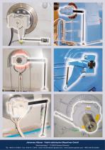
Johannes Hübner · Fabrik elektrischer Maschinen GmbH Siemensstrasse 7 · D-35394 Giessen/Germany Tel. +49 6 41/ 79 69-0 · Fax +49 6 41/ 7 36 45 · email: [email protected] · www.huebner-giessen.com · HRB 126 AG Gi
Open the catalog to page 8All Johannes Hübner Giessen catalogs and technical brochures
 A...40/41
20 Pages
 Looper encoder AL...40
12 Pages
 Simplifying Cranes
12 Pages
 Cable protection systems
12 Pages
 U-ONE®(-SAFETY)-LWL and -Compact
36 Pages
 U-ONE
U-ONE24 Pages
 EGS inquiry form
2 Pages
 U-ONE Inquiry form
2 Pages
 U-ONE / U-ONE SAFETY
8 Pages
 A...40/41 Inquiry forms
2 Pages
 MAG inquiry form
5 Pages
 EDU 100
2 Pages
 TDP ...
4 Pages
 Synchron-Servo-Motoren
6 Pages
 DSG P-series
20 Pages
 Ex FG 40 inquiry form
2 Pages
 NEWS-Flyer Ex FG 40
2 Pages
 Program overview
6 Pages
 G ... / GN ... Inquiry form
2 Pages
 DSG P ... Inquiry form
2 Pages
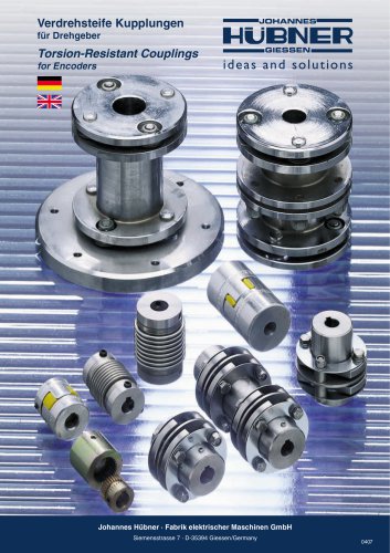 Couplings
20 Pages
 Frequency voltage converter
8 Pages
 Pulse converter
2 Pages
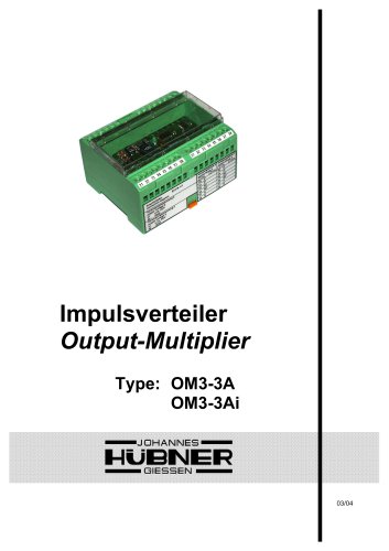 Output multipliers
10 Pages
 FOC Accessories
16 Pages
 DSG P ... (Generators)
20 Pages
 G ... / GN ... (DC motors)
16 Pages
 MGDDP
MGDDP4 Pages
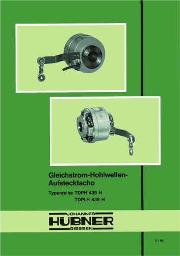 TDP H 439 H
8 Pages
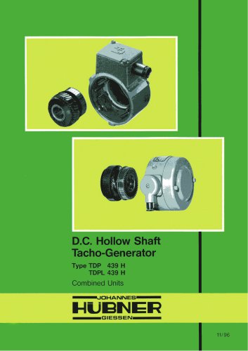 TDP 439 H
4 Pages
 TDP 0,7 SE
1 Page
 AMPNH 41
2 Pages
 AMPN 41
2 Pages
 AMPH 41
2 Pages
 AMP 41
2 Pages
 FGH 5-6-8-14-20
76 Pages
 Image brochure
16 Pages
 Crane and harbor technology
8 Pages



Archived catalogs
 Tacho generators TDP
8 Pages
 FG(HJ) 2
12 Pages

- Johannes Hübner rotary encoder
- Servo-motor
- Johannes Hübner incremental rotary encoder
- Flexible coupling
- Shaft shaft coupling
- Johannes Hübner absolute rotary encoder
- Johannes Hübner solid-shaft rotary encoder
- Johannes Hübner optical rotary encoder
- Johannes Hübner industrial rotary encoder
- Generator
- Johannes Hübner hollow-shaft rotary encoder
- Magnetic rotary encoder
- Flange coupling
- Limit switch
- Johannes Hübner IP67 rotary encoder
- Compact rotary encoder
- Johannes Hübner aluminum rotary encoder
- Johannes Hübner DC rotary encoder
- Stainless steel rotary encoder