USR-N668
1 /48Pages

USR-N668
1 /48Pages
Catalog excerpts

Technical Support: h.usriot.com Jinan USR IOT Technology Limited
Open the catalog to page 1
Technical Support: h.usriot.com
Open the catalog to page 2
Technical Support: h.usriot.com Jinan USR IOT Technology Limited
Open the catalog to page 3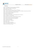
Technical Support: h.usriot.com Two 10/100Mbps Ethernet port, support Auto-MDI/MDIX. 8 serial ports all support RS232/RS485/RS422. Support Static IP or DHCP. TCP Server, TCP Client, UDP Client, UDP Server, HTTPD Client . 8 serial ports all support two sockets ,and all can send data to two different servers when work as Client. It works as TCP client, supports to 16(max) TCP Client. Keep-alive & Registration-package. Modbus TCP to Modbus RTU. User-defined overtime Reload (no data reload)and overtime connection. The modifiable , one and only MAC. DNS domain name resolution ,user-defined DNS server...
Open the catalog to page 4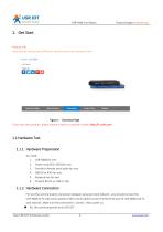
Technical Support: h.usriot.com 1. Get Start Product link: http://usriot.com/products/8-ports-serial-to-ethernet-converter.html Figure 1 Download Page If you have any question, please submit it back to customer center: http://h.usriot.com 1.1.Hardware Test 1.1.1. Hardware Preparation You need: 1. USR-N668 for one; 2. Power cord (85V~265V)for one; 3. Female to female serial cable for one; 4. DB9-M to RJ45 for one; 5. Network line for two; 6. PC(with RS232,or USB to 232) 1.1.2. Hardware Connection For test the communication conversion between serial port and network , you should connect the USR-N668...
Open the catalog to page 5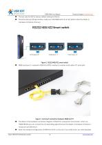
Technical Support: h.usriot.com The test only for RS232, factory default setting for RS232; Check the dial up settings window ,make sure USR-N668 work at correct pattern.(See the details in Hardware introduce->Dial up) Figure 1. RS232/485/422 smart switch N668 serial port 1->network->DB9-M to RJ45->mother to mother serial cable->PC serial port Figure 2. serial port connection between N668 and PC The above is the hardware connection diagram of RS232 for transparent transmission. when use RS485/RS422,you can connect the corresponding signal line.(see the details in Hardware introduce-> Serial port...
Open the catalog to page 6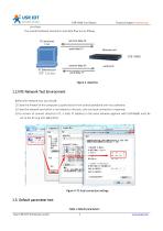
Technical Support: h.usriot.com purchase The overall hardware connection and data flow are as follows, Figure 3. data flow 1.2.NTE Network Test Environment Before the network test, you should: 1) Close the firewall of the computer (usually found in the control panel)and anti-virus software; 2) Close the network card which is not related to this test, only one local connection is reserved; 3) For servers to connect directly to PC, a static IP (address in the same network segment with USR-N668) must be set to the PC (e.g.192.168.0.201). Figure 4. PC local connection settings 1.3. Default parameter...
Open the catalog to page 7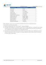
Technical Support: h.usriot.com User name Password IP address Subnet mask Default gateway Default mode of operation Default target port Default local port Default target IP Serial baud rate Serial port parameters After confirmation, You can carry out the bidirectional between the serial port and the Ethernet port. Communication procedures are as follows: 1) Open the testing software”USR-TCP232-Test.exe”,connected hardware; 2) The default mode of operation is TCP Server, first port serial port monitor 20001 port. So choose TCP client mode at the network setup end of the software,IP:192.168.0.7,target...
Open the catalog to page 8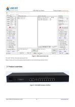
Technical Support: h.usriot.com Figure 5. data transmission test The USR-TCP232-Test.exe download links: https://www.usriot.com/support/downloads/usr-tcp-test-testing-software.html Figure 6. USR-N668 hardware interface Jinan USR IOT Technology Limited
Open the catalog to page 9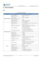
Technical Support: h.usriot.com 2.1. Basic parameters 2.2. Table 2 Electrical parameters Hardware parameters parameter Working voltage Power Consumption Ethernet Port Number of Ethernet port Serial port format Number of serial port Serial baud rate Network protocol IP Domain name resolution numerical AC 85~265V, 50/60Hz 1.6W RJ45、10/100Mbps 2 RJ45 8*RS232/RS485/RS422 300-115.2K(bps) IP、TCP/UDP、ARP、ICMP、IPV4、HTTP、SSL Static IP、DHCP Support, customize DNS server address Software configuration, Web page configuration, AT instruction configuration TCP Server/TCP Client/SSL Client UDP Server/UDP Client/Http...
Open the catalog to page 10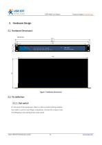
Technical Support: h.usriot.com 3. Hardware Design 3.1. Hardware Dimensions Figure 7 Hardware dimensions 3.2. Pin definition 3.2.1. Dial switch On the back of the equipment, there is a dial up switch setting window. You need to use the cross flower screwdriver, remove the screws to see. The following is the setting of the code switch. Jinan USR IOT Technology Limited
Open the catalog to page 11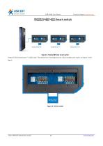
Technical Support: h.usriot.com Figure 8. RS232/485/422 smart switch A total of 16 (8 serial port * 2) dial code. The device has 8 serial ports and 2 dial numbers per route, as shown in the figure. Jinan USR IOT Technology Limited
Open the catalog to page 12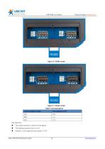
Technical Support: h.usriot.com Figure 11. RS422 model Table 3 Correspondence Pay attention: The switch position is shown in the figure. The dialing sequence form L to R. Default is 232 mode,the dial switch is “0 0”. Jinan USR IOT Technology Limited
Open the catalog to page 13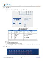
Technical Support: h.usriot.com 3.2.2. Pin definition The serial port pin diagram is as follows (The hardware interface is RJ45). Figure 12. Serial line sequence Table 4 Serial line sequence Pin Number Pay attention: 232,485,422 can’t work at one time; The position of the dialing switch must be correct. The hardware interface is RJ45, you need to use 8 core cable and crystal head to make communication cables. Figure 13. LED location Jinan USR IOT Technology Limited
Open the catalog to page 14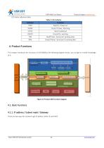
Technical Support: h.usriot.com LED status reference table. Table 5 LED indicator Indicator PWR WORK STATE READY TXN RXN Function Red/On: Power on Green/ Flicker: Working Red/ Undefined Green/On: working Red/Flicker: Serial port sending data Green/Flicker: Serial port receiving data 4. Product Functions This chapter introduces the functions of USR-N668 as the following diagram shown, you can get an overall knowledge of it. Figure 14 Product 668 Functions diagram 4.1. Basic Functions 4.1.1. IP address / Subnet mask / Gateway There are two ways for module to get IP address: Static IP and DHCP....
Open the catalog to page 15All Jinan USR IOT Technology Limited catalogs and technical brochures
 USR-MB706
2 Pages
 USR-G807
6 Pages
 USR-N520-H7-6
5 Pages
 USR-G786-G
2 Pages
 USR-LG206-P
15 Pages
 USR-M511
19 Pages
 USR-K6
107 Pages
 USR-K5
81 Pages
 USR-TCP232-306
23 Pages
 USR-DR302
70 Pages
 USR-DR301
70 Pages
 USR-DR404
86 Pages
 USR-GPRS232-734
15 Pages
 USR-W630
34 Pages
 USR-W610
4 Pages
 USR-WIFI232-B2
1 Page
 USR-WIFI232-A2
1 Page
 USR-GM3
2 Pages
 USR-SDR021
4 Pages
 USR-SDR041
3 Pages
 USR-SDR080
3 Pages
 USR-SDR160
3 Pages
 USR-K7
1 Page
 USR-CANET200
3 Pages
 USR-TCP232-S2
1 Page
 USR-TCP232-T2
1 Page
 USR-GPRS232-730
2 Pages
 GW-R4513
5 Pages
 USR-TCP232-304
1 Page
 USR-TCP232-302
1 Page
 USR-G806-A
6 Pages
 USR-G806-E/AU
6 Pages
 USR-TCP232-ED2
4 Pages
 USR-TCP232-E2
4 Pages
 USR-N540
5 Pages
 USR-N510
5 Pages
 USR-N520
5 Pages
 USR-N580
5 Pages
 USRIOT USR-G800V2 catalogs
7 Pages
 USR-GPRS232-7S3
2 Pages
 USR-SDR050-L
4 Pages


- Ethernet switch
- Industrial network switch
- DIN rail mounted network switch
- Waterproof network switch
- Communication gateway
- Unmanaged switch
- Redundant network switch
- PoE network switch
- Industrial gateway
- Ethernet gateway
- Fieldbus gateway
- Industrial communication router
- Serial gateway
- Ethernet communication router
- DIN rail converter
- IP40 network switch
- Communication router with VPN
- Ethernet converter
- Fast network switch
- 8 ports network switch