- Catalogs
- Jiangsu Jwc Machinery Co., Ltd.
- TECHMAC Defect Detection System Manual v2.0
TECHMAC Defect Detection System Manual v2.0
1 /29Pages

TECHMAC Defect Detection System Manual v2.0
1 /29Pages
Catalog excerpts
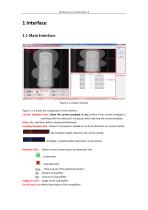
1 Interface 1.1 Main Interface Figure1.1-1 Main Interface Figure 1.1-1 shows the composition of the interface. Current Template name: Show the current template in use.Confirm if the current template is matching with the products,if not,please select and load the correct template. Menu: ALL operation will be introduced afterwards. Loarding Template Info.: Shows if a template is loaded or not,if not,detection can not be started. : No template loaded, detection can not be started. : Template is already loaded, detection can be started. Detection Info.: Shows current system status and detection info....
Open the catalog to page 3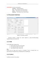
Control button: commonly used operation。 Start/Stop: Start/Stop Detection Zero: Zero the detection information and list Correct: Will Introduce more in latter chapter Reset Para: Will introduce more in latter chapter Figure1.2-1 Parameters Interface Parameter Interface is divided into several segments as path,control,Result,Debug Log,Reject Wasted ,and rejection test. 1.2.1 Path Set up storage path of image and log 1) Normal Image: Save path of normal image 2) Error Image: Save path of error image 3) Log: Storage Save path of system log Note: Normal and error image will be stored in H disk.When...
Open the catalog to page 4
1) Show Image: shows if the image area display detection photos 2) Show Information: shows if the image area display template loading info. 3) Save error Image: click to save image,otherwise not.Fault images will be not saved. 4) Auto start : check this will enable the running system to start detection automatically 5) Save normal image : Ensure normal images are saved 1.2.3 Result Results List Display 1) Show Error Result: showing defect information on the results list or not 2) List Record Number: Maximum number of results record on the list 1.2.4 Debug Log This is for programmer.Normally,...
Open the catalog to page 5
4) Normal: Implementing waste rejection according to the result.The waste rejection order is executed depending on if there is defect 5) Continuity: every piece will be ordered to do waste rejection ignoring the detection results. 6) Interval: every two pieces will be ordered to do waste rejection ignoring the detection results. Note: a、Continuous Waste Rejection and Skip waste rejection are for testing correctness of waste picking position b、Both OUT0 and OUT11 are for testing if there is correct waste rejection output and if the connections are good. Precaution:All data should check “apply”...
Open the catalog to page 6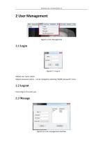
Figure2.1-1 Log on Default user name: admin Default password: admin,can be changed by selecting “Modify password” menu 2.2 Logout Cancel log-in of current user
Open the catalog to page 7
Administrator has the right to manage all the users.See Figure2.3-1.
Open the catalog to page 8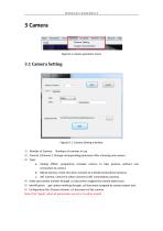
Figure3-1 camera operation menu Figure3.1-1 Camera Setting interface 1) Number of Camera: Numbers of cameras in use. 2) Camera 1/Camera 2: Change corresponding parameter after choosing one camera. 3) Type: a、 Analog offline: programme simulate camera to take pictures without real connection to camera. b、 DALSA Camera: check this when connect to a DALSA camera(Line Camera). c、 AVT Camera: Check this when connect to AVT camera(Area camera). 4)Index: get camera number through .ccf document assigned by camera expert tool. 5)Identification: get camera marking through .ccf document assigned by camera...
Open the catalog to page 9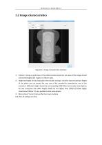
Figure3.2-1 Image characteristics Interface 1) Position: Tuning up and down of the photo location,maximum set value of the image should not exceed height.Click “apply” to make it valid. 2) Height:set height of the photo,when the encoder turning 1 circle for 1piece,maximum height of the photo can not exceed the max row of the encoder.For example,max row of the encoder is 2500,max height should be not exceeding 2500.When the encoder treat 2pieces for one circle,then the photo height should be not higher than 2500/2=1250.we highly recommend 1240,or it’s very possible to lose some phases. 3) Mirror:check...
Open the catalog to page 10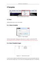
Figure4-1 Template Operation Menu 4.1 New Following below steps to creat a new template Figure4.1.1-1 Name Template Click”creat new template”,a dialog pops up like picture 4.1.1-1,put in a name and click “OK”. Note:Template name can not be blank or same with existed template,or you can not move on. 4.1.2 Save Template Images Figure4.1.2-1 Normal picture records In real time picture display area,double right-click will save the normal pictures(double right-click twice will cancel saving).If two or more cameras are working,doub
Open the catalog to page 11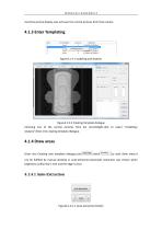
real-time picture display area will save the normal pictures from that camera. Figure4.1.3-2 Creating Template dialogue Choosing one of the normal pictures from list record;Right-click to select “modeling| Analysis”;Enter into creating template dialogue. 4.1.4 Draw areas Enter into Creating new template dialogue,click ,to start draw areas.It can be fulfilled by manual drawing or auto-extraction.Automatic extraction was chosen when brightness uniformity is met and the edge is clear.
Open the catalog to page 12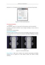
See picture 4.1.1.1-1 for operation of Auto-extraction.How to use and function of each button, Figure4.1.4.1-2 Auto-extraction parameters Auto-extraction Parameters Click , Figure4.1.4.1-2 pops up,this is all the parameters used in auto-extraction. As products varies,relevant parameters may be changed accordingly to ensure accurity of auto-extraction. Each parameter is introduced below: Regional quantity coefficient: Revising the number can decide how many will be extracted.Bigger the digit,smaller the quantity or vice versa.Picture 4.1.4.1-3 shows real circumstance under different RQC(Regional...
Open the catalog to page 13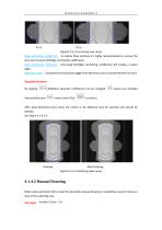
FC=5 Figure4.1.4.1-4 scanning area cavity Edge contraction coefficient: To reduce false positives,it’s highly recommended to narrow the area and increase ECC(Edge contraction coefficient). Edge smoothing coefficient: Increasing ESC(Edge smoothing coefficient) will enable a neater egde. Minimum Area: Extracted area should be bigger than Minimum area to avoid interference area. Operation buttons: By tapping ,AQC(Area Quantity coefficient) can be changed. means more.Click means less extrated After Auto-extraction,some areas not meant to be detected may be selected and should be deleted. See Figure...
Open the catalog to page 14All Jiangsu Jwc Machinery Co., Ltd. catalogs and technical brochures


- Welding system
- Packing machine
- Crushing plant
- Automatic packaging machine
- Making machine
- Bagging machine
- Stationary crushing plant
- Inspection system
- Automatic production machine
- Disinfection unit
- Standalone welding machine
- Horizontal bagging machine
- Desktop printer
- Quality inspection system
- Semi-automatic welding machine
- Stationary decontamination unit
- Automatic counting machine
- Production inspection system
- Computer-controlled inspection system
- Application head