- Catalogs
- Jiangsu Gtake Electric Co., Ltd.
- SLR01A_Manual for Solar Water Pump Drive
SLR01A_Manual for Solar Water Pump Drive
1 /230Pages

SLR01A_Manual for Solar Water Pump Drive
1 /230Pages
Catalog excerpts
Think Without Boundary User Manual Solar Pump Drives 3AC 400V 0.75~75k\A/
Open the catalog to page 1
JIANGSU GTAKE ELECTRIC CO., LTD. reserves the right to modify the frame dimensions, functionality, technical data, parameters, standards without prior notice. No part of this manual may be reproduced, stored in a retrieval system, or transmitted, in any form, or by any means, without prior written permission of GTAKE. We have checked the contents of this manual for accordance with its described hardware and software. However, the contents of this manual may be subject to appropriate modification as a result of product upgrade, specification change and update of the manual, we cannot guarantee...
Open the catalog to page 2
Thank you for choosing GTAKE SLR01A Series Solar Water Pump Drives. This user manual presents a detailed description of SLR01A series with respect to product features, structural characteristics, functions, installation, parameter settings, troubleshooting, commissioning and daily maintenance, etc. Be sure to carefully read through the safety precautions before use, and use this product on the premise that personnel and equipment safety is ensured. ■ Please assure the intactness of product enclosure and all safety covers before installation .Operation must conform to the requirements of this...
Open the catalog to page 3
Before installation, wiring, operation, and repair to the drive, please read carefully and strictly comply with all its Safety Precautions in this manual. Please ensure all the warning marks on the drive are clear and distinct. Replace or add the obscure or missed warning marks. The information from following sources is all effective. Telephone: +86 755 8639 2601 Fax: +86 755 8639 2625 Email: [email protected], [email protected] Monday to Friday: 8:30 a.m. to 18:00 p.m. (Beijing time) Users may acquire general technical data and information through GTAKE official website: http://www. gtake. com,...
Open the catalog to page 4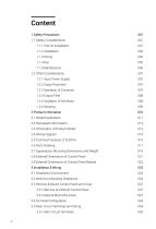
1.2.1 Input Power Supply 007 2.3 Information of Product Model 013 2.7 Appearance, Mounting Dimensions and Weight 019 2.8 External Dimensions of Control Panel 021 2.9 External Dimensions of Control Panel Bracket 022 3.2 Minimum Mounting Clearances 024 3.3 Remove & Mount Control Panel and Cover 027 3.3.1 Remove and Mount Control Panel 027 3.3.2 Open & Mount the Cover 027 3.5 Main Circuit Terminals and Wiring 034 3.5.1 Main Circuit Terminals 035
Open the catalog to page 5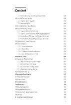
3.5.2 Terminal Screw and Wiring Requirement 038 3.6 Control Terminal Wiring 038 3.6.1 Control Board Diagram 039 3.7 Control Terminal Specification 042 3.8 Control Terminal Usage 044 3.8.1 Lay-out of Control Terminals 044 3.8.2 Control Terminal Screw and Wiring Requirement 044 3.8.3 Instructions of Analog Input/Output Terminals 044 3.8.4 Instructions of Digital Input/Output Terminals 045 3.9 Instruction of Signal Switches 051 3.10.3 Leakage Current Suppression 054 3.10.4 Use of Power Supply Filter 055 4.1 Operation of Control Panel 057 4.1.1 Key Functions on Control Panel 057 4.1.2 Control Panel...
Open the catalog to page 6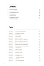
Figure 2-1 Figure 2-2 Figure 2-3 Figure 2-4 Figure 2-5 Figure 2-6 Figure 2-7 Figure 3-1 Figure 3-2 Figure 3-3 Figure 3-4 Figure 3-5 Figure 3-6 Figure 3-7 Figure 3-8 Figure 3-9 Figure 3-10 Figure 3-11 Figure 3-12 Product model explanation Nameplate information Wiring diagram Parts drawing External dimensions External dimensions of KBU-BX1 External dimensions of KBU-DZ1 Minimum mounting clearances A Minimum mounting clearances B Remove / Mount the control panel Open the Cover I Mount the Cover I Open the Cover II Mount the Cover II Open the Cover III Mount the Cover II Terminal configuration Terminals...
Open the catalog to page 7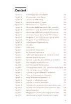
Figure 3-13 Solar panel DC input wiring diagram 040 Figure 3-14 AC power supply wiring diagram 041 Figure 3-15 Lay-out of control terminals 044 Figure 3-16 Internal power supply dry contact 046 Figure 3-17 External power supply dry contact 046 Figure 3-18 Internal power supply open collector NPN connection 047 Figure 3-19 External power supply open collector NPN connection 048 Figure 3-20 Internal power supply open collector PNP connection 049 Figure 3-21 External power supply open collector PNP connection 049 Figure 3-22 Wiring when Y1 and Y2/DO output with pull-up resistor 050 Figure 3-23 Wiring...
Open the catalog to page 8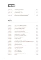
Figure 5-4 Pump cleaning sequence 091 Figure 5-5 Maximum frequency 100 Figure 5-6 PQ performance curve 151 Figure A-1 Single master/multiple slaves networking 191 Figure A-2 Single master/Single slave networking 192 Table 2-1 SLR01A input voltage requirement 013 Table 2-2 SLR01A model and technical data 013 Table 3-1 Terminal screw and wiring requirement 038 Table 3-2 Control terminal specification 042 Table 3-3 Terminal screw and wiring specification 044 Table 4-1 Key functions on control panel 057 Table 4-2 MF key function definition (L0-00) 058 Table 4-3 Description of indicators 059 Table...
Open the catalog to page 9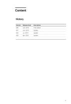
Version Release Date Description A00 Jan. 2018 First edition
Open the catalog to page 10
Safety Precautions
Open the catalog to page 11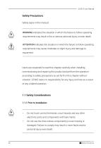
Safety Precautions Safety signs in this manual: WARNING indicates the situation in which the failure to follow operating requirements may result in fire or serious personal injury or even death. ATTENTION indicates the situation in which the failure to follow operating requirements may cause moderate or slight injury and damage to equipment. Users are requested to read this chapter carefully when installing, commissioning and repairing this product and perform the operation according to safety precautions as set forth in this chapter without violation. GTAKE bears no responsibility for any injury...
Open the catalog to page 12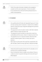
Check if the product information indicated on the nameplate is consistent with the order requirements. If not, do not install it. Do not install the drive in the event that the packing list does not match the real equipment. 1.1.2 Installation • Only qualified personnel familiar with adjustable frequency AC drives and solar pumping system should plan or implement the installation. Failure to comply may result in equipment damage and/or personnel injury even death. • This equipment must be mounted on metal or other flame retardant objects. Failure to comply may result in fire. • This equipment...
Open the catalog to page 13All Jiangsu Gtake Electric Co., Ltd. catalogs and technical brochures
 Battery Simulator for Test Bench
16 Pages
 2-Wheeler Motor Controller
12 Pages
 GK1000
4 Pages
 GK600
GK6006 Pages
 GK800
GK8005 Pages
 SLR01
SLR016 Pages
 GS100M
2 Pages
 GK 600E
4 Pages
 GK500
GK5002 Pages
 Solar Pump Drive
3 Pages
 GSM100M
2 Pages
 KTZ X50FBB01
4 Pages
 Product Catalog
50 Pages
- Test stand
- DC-DC converter
- Motor controller
- Frequency inverter
- DC motor controller
- 3-phase AC drive
- Test station for the automotive industry
- 3-phase frequency converter
- Brushless motor control
- Digital input motor controller
- AC motor controller
- Compact motor controller
- Motor controller with speed control
- Programmable motor controller
- Digital output motor controller
- Analog input motor controller
- Closed-loop motor controller
- Digital motor controller
- Motor frequency converter