Catalog excerpts
Simple Tuner Pro GUI Guide Line Quick GUI User Guide DINGS’ Simple Tuner Pro GUI
Open the catalog to page 1
Motor Parameter Setti
Open the catalog to page 2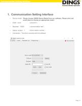
Communication Setting Interface 1. Communication Setting Interface • Device model:Please choose DINGS Device Model from our software. Please click and scroll down to choose an appropriate model. (communication rate) (Driver station number) Connection : The driver connects wi
Open the catalog to page 3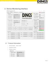
Device Monitoring Interface 2. Device Monitoring Interface Product Model: Driver model Hardware version: Software version:
Open the catalog to page 4
Device Monitoring Interface Pulse mode:1 pulse, 2 pulse mode 2.3 Operation Parameters and Control
Open the catalog to page 5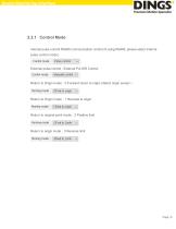
Device Monitoring Interface 2.3.1 Control Mode Internal pulse control RS485 communication control (if using RS485, please select internal pulse control mode) External pulse control : External Pul DIR Control Return to Origin mode:0 Forward return to origin (detect origin sensor) Return to Origin mode:1 Reverse to origin Return to original point mode:2 Positive limit Return to origin mode:3 Reverse limit
Open the catalog to page 6
Device Monitoring Interface Position mode speed :1000 (running speed) Jog mode speed :100 (Jog speed) Set position: 0 (set the current position value) Original offset pulse :0 Velocity mode speed :1000 Operation pulse :0(Number of shift pulses) Relative position : relative position movement Absolute position : absolute position movement Forward jogging : Jog+ Positive movement : Move+ Negative movement : Move- Constant speed mode : speed mode motion Deceleration stop: deceleration stop motion Return to origin : 回 Return to origin movement (find the origin sensor)
Open the catalog to page 7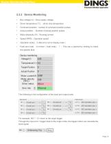
Device Monitoring Interface Bus voltage (V) : Drive supply voltage Driver temperature (℃) :driver chip temperature Command position : number of command position pulses Actual position :Number of actual position pulses Motor electricity (A):Running current Speed (RPS):Operation speed Operation status:0 data error (error display code) Fault and code :0 normal (fault code) ?: This can e opened by clicking to check the specific fault This following is the configuration of the input and output ports For example, IN1○ 12: return to the origin trigger. Through the input port 1 trigger back to the...
Open the catalog to page 8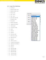
Device Monitoring Interface 2.3.3 Input Port Definition • 1: Absolute position start 2: Relative position start 6 : Slow down and stop 9: Positive limit signal 10: Negative limit signal 16: Multi axes start 17: Multi axes pause 21 : Forward move (Move+) 22 : Reverse move (Move-)
Open the catalog to page 9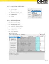
Device Monitoring Interface 2.3.4 Output Port Configuration • 101: No alarm status output 102: Positioning complete output 01: Basic parameter setting 02: Motor parameter setting 03: Closed loop parameter setting 04: Control parameter setting 05: Input port setting
Open the catalog to page 10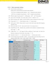
Device Monitoring Interface 2.3.5.1 Basic parameter setting 201 : motor direction switching 0~3 (select motor running direction and set encoder direction: bit1=0 do not change encoder direction、bit1=1: change encoder direction; bit0=0 do not change running direction、bit0=1: change running direction 202 : Effective edge of pulse signal 0~1(falling edge:set“0”,set“1”rising edge) 241 : Input current 100~3200(set current value, Unit mA,1000mA = 1A.) 242 : Set the resolution 200~102400(set the resolution value to indicate the number of ppr) 244 : Pulse mode 1~2 (1:Pulse direction mode。2:2 pulse...
Open the catalog to page 11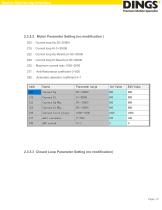
Device Monitoring Interface 2.3.5.2 Motor Parameter Setting (no modification) 200: Current loop Kp 50~20000 215: Current loop Ki 0~30000 222: Current loop Kp Maximum 50~30000 228: Current loop Ki Maximum 50~20000 225 : Maximum current ratio 1000~2000 277: Anti-Resonance coefficient 0~500 295: Automatic detection coefficient 0~1 2.3.5.3 Closed Loop Parameter Setting (no modification)
Open the catalog to page 12
Device Monitoring Interface 2.3.5.4 Control Parameter Setting 301:Start speed 1~1000 (start speed, effective internal pulse 0.01rps ,unit. ) 302 : Stop speed 1~1000(stop speed, effective internal pulse 0.01rps ,unit.) 303: acceleration 5~10000 (acceleration, effective internal pulse rps2,unit ) 304 : deceleration 5~10000(deceleration,effective internal pulse, unit rps2) 305:return to origin mode 0~10 (back to the origin mode, the internal pulse is valid。 0:forward return to origin; 1:reverse to the origin; 2:forward return limit; 3:reverse return limit; Other : Invalid.) 306:position mode...
Open the catalog to page 13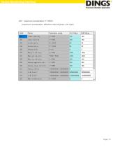
Device Monitoring Interface combination and multi axes IO triggers execution 325 : maximum acceleration 5~10000 (maximum acceleration, effective internal pulse, unit rps2)
Open the catalog to page 14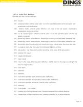
Device Monitoring Interface 2.3.5.5 Input Port Settings 400~406 IN1~IN7 function selection 000:Invalid; 001:absolute motion, internal pulse valid : run to the specified position at the set speed and acceleration and deceleration 002 : relative motion, internal pulse effective: run once at the set speed, acceleration, deceleration and pulse number 003:run at constant speed, effective internal pulse: run at the specified speed until the top speed is received 004:forward jog, internal pulse effective : forward jog according to the set speed, release to stop 005:reverse jog, internal pulse...
Open the catalog to page 15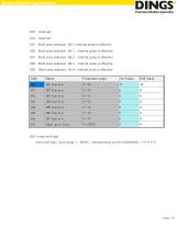
Device Monitoring Interface 023:reserved; 024:reserved; 025:Multi axes selection Bit 0, internal pulse is effective 026:Multi axes selection Bit 1,internal pulse is effective 027:Multi axes selection Bit 2,internal pulse is effective 028:Multi axes selection Bit 3,internal pulse is effective 029 : Multi axes selection Bit 4 , internal pulse is effective 429 : Input port logic (input port logic, input range :1~65535,corresponding port [8:1]:000000
Open the catalog to page 16
Device Monitoring Interface 2.3.5.6 Output Port Settings 420~423 Out1~ Out 4 function selection 100:general output, the status is controlled by the value of address:0459 value control of the system; 101:alarm output function: there is output signal when no alarm, there is no output signal when alarm. It can be used for holding brake control output function and external relay is required after optocoupler output (brake lead is connected to normally open contact, that is, it is powered on when there is no alarm) 102 : positioning completion output function. output signal when the motor...
Open the catalog to page 17All Jiangsu DINGS' Intelligent Control Technology Co. catalogs and technical brochures
-
 Simple Brochure
8 Pages
-
 General Catalog
354 Pages
-
 DS-BVS-FETC-FCAO_Hardware Manual
18 Pages
-
 DS-BVS-BVM-Series_Reference Manual
181 Pages
-
 DINGS Servo Studio Manual
57 Pages
-
 DS-BVM-FETC-FCAO_Hardware Manual
15 Pages
-
 DS-OL42-ICAO_Technical Manual
53 Pages
-
 DS-CLS9-FETC-2I_Technical Manual
43 Pages
-
 DS-CLS9-FETC-2A_Technical Manual
43 Pages
-
 DS-CLS9-FETC_Technical Manual
17 Pages
-
 DS-CLS9-FCAO_Technical Manual
59 Pages
-
 DS-OLS10-FSC_Technical Manual
12 Pages
-
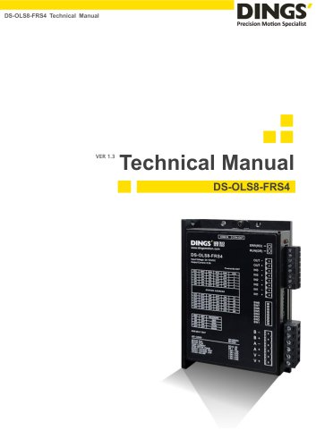 DS-OLS8-FRS4_Technical Manual
30 Pages
-
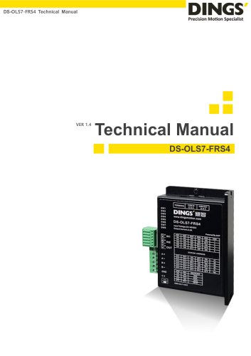 DS-OLS7-FRS4_Technical Manual
29 Pages
-
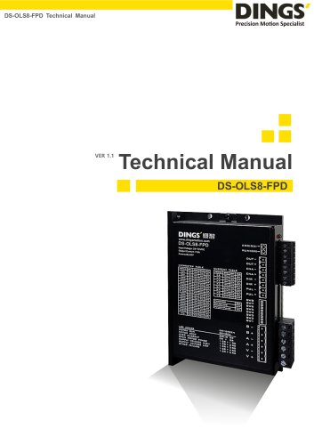 DS-OLS8-FPD_Technical Manual
16 Pages
-
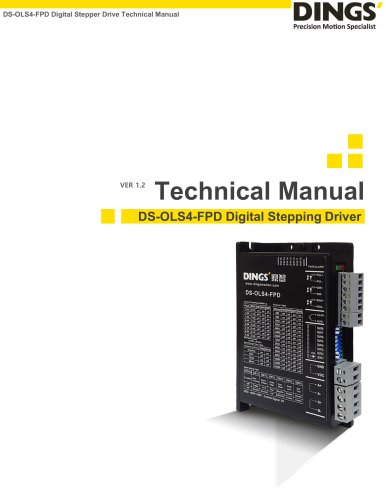 DS-OLS4-FPD_Technical Manual
17 Pages
-
 DS-OLS22_FPD_Technical Manual
16 Pages
-
 DS-OLS2-FPD_Technical Manual
16 Pages
-
 DS-CLS9-FRS4_Technical Manual
21 Pages
-
 DS-CLS9-FRS4-01_Technical Manual
29 Pages