Catalog excerpts
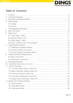
Pulse Signal : STEP………………………………………….………………………………..11 Direction Signal : DIR………………………………………………………………………….11 Offline Signal : FREE…………………….…………………………………………………….12 Pulse / Direction Input Timing Diagram……………………………………………………..12 7. Typical Signal Connection…………………………………………………………………………..13 7.1 Differential Connection Method………………………………………………………………13 7.2 Common Positive Connection………………………………………………………………13 7.3 Common female Connection Method…………………………………………
Open the catalog to page 2
1. Features Input power: DC 24V-72V It has offline function, adopts RS-485 isolated bus, supports standard MODBUS-RTU protocol, and can mount up to 30 devices Bus-type driver can realize long-distance reliable control, effectively solve the problem of pulse loss in interference environment The user can set the current, subdivision and lock current, running mode (pulse input mode, point control mode) through the bus; Run real-time status queries Built-in single-axis controller function: users can set parameters such as start speed, acceleration time, deceleration time, maximum...
Open the catalog to page 3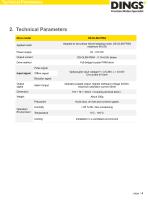
Technical Parameters 2. Technical Parameters Drive model Applied motor Adapted to two-phase hybrid stepping motor, DS-OLS8-FRS4 maximum fit 6.5A Power supply Output current Drive method Full-bridge bi-polar PWM drive Pulse signal Input signal Offline signal Optocoupler input voltage H = 3.5-26V, L = 0-0.8V On-current 6-15mA Direction signal Output signal Alarm Output Operation Environment Optically isolated output, highest withstand voltage 30VDC, maximum saturation current 50mA Humidity Temperature Cooling Avoid dust, oil mist and corrosive gases < 85 % RH, Non-condensing 0°C - +40°C...
Open the catalog to page 4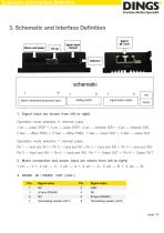
Schematic and Interface Definition 3. Schematic and Interface Definition 1. Signal input (as shown from left to right) Operation mode selection 0: external pulse 1 pin --- pulse STEP +, 2 pin --- pulse STEP-, 3 pin --- direction DIR +, 4 pin --- direction DIR5 feet --- offline FREE +, 6 feet --- offline FREE-, 7 feet --- output OUT +, 8 feet --- output OUTOperation mode selection 1: internal pulse Pin 1 --- Input port IN1 +, Pin 2 --- Input port IN1-, Pin 3 --- Input port IN2 +, Pin 4 --- Input port IN2Pin 5 --- Input port IN3 +, Pin 6 --- Input port IN3-, Pin 7 --- Output OUT +, Pin 8 ---...
Open the catalog to page 5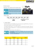
Schematic and Interface Definition Standard product: RJ45 type × 2 Pin position from the insertion angle When multiple units are connected in series, when pins 3 and 8 of the last OUT port are short-circuited, and pins 6 and 7 are shortcircuited, it is the access terminal resistance. The IN port does not include a terminating resistor. Setting switch 4. mailing address Users can control up to 30 HSD286pro drives at the same time using RS-485 bus. The driver's communication address is set by a 5-digit DIP switch. The address setting range is 1-32, where address 32 is reserved for the system....
Open the catalog to page 6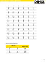
Schematic and Interface Definition 5. Communication baud rate DIP switch Baud rate(bps)
Open the catalog to page 7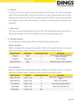
Schematic and Interface Definition 6. Trial run The test run function is used to verify the performance of the drive. Turn OFF the 8th gear switch in the power-off state. Then when the power is turned on without pulse input, turn the SW8 gear dial switch from ON to OFF, and then set OFF to ON from 1 second, then start the trial operation function (the motor rotates at 1 revolution / second Speed cycle forward and backward). 7. Idle current The driver will automatically enter idle current after 500 milliseconds without pulse input to reduce motor heating. The current is restored to the set...
Open the catalog to page 8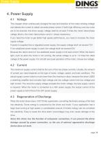
Power Supply The chopper driver continuously changes the size and direction of the motor winding voltage and detects the current to obtain accurate phase current. If both high efficiency and low noise are to be ensured, the driver supply voltage shall be at least 5 times the motor rated phase voltage (that is, the motor rated phase current × phase resistance). If you need the motor to get better high speed performance, you need to increase the driver supply voltage. If power is supplied from a regulated power supply, the supply voltage shall not exceed 72V. If non-stabilized power supply is...
Open the catalog to page 9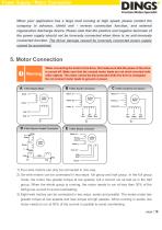
Power Supply / Motor Connection When your application has a large load running at high speed, please contact the company in advance, shield anti - reverse connection function, and external regenerative discharge device. Please note that the positive and negative terminals of the power supply should not be inversely connected when there is no anti-inversely connected function. The driver damage caused by inversely connected power supply cannot be guaranteed. 5. Motor Connection Warning When connecting the motor to the drive, first make sure that the power of the drive is turned off. Make...
Open the catalog to page 10All Jiangsu DINGS' Intelligent Control Technology Co. catalogs and technical brochures
-
 General Catalog
295 Pages
-
 Simple Brochure
36 Pages
-
 DS-BVS-FETC-FCAO_Hardware Manual
18 Pages
-
 DS-BVS-BVM-Series_Reference Manual
181 Pages
-
 DINGS Servo Studio Manual
57 Pages
-
 DS-BVM-FETC-FCAO_Hardware Manual
15 Pages
-
 DS-OL42-ICAO_Technical Manual
53 Pages
-
 DS-CLS9-FETC-2I_Technical Manual
43 Pages
-
 DS-CLS9-FETC-2A_Technical Manual
43 Pages
-
 DS-CLS9-FETC_Technical Manual
17 Pages
-
 DS-CLS9-FCAO_Technical Manual
59 Pages
-
 DS-OLS10-FSC_Technical Manual
12 Pages
-
 DS-OLS7-FRS4_Technical Manual
29 Pages
-
 DS-OLS8-FPD_Technical Manual
16 Pages
-
 DS-OLS4-FPD_Technical Manual
17 Pages
-
 DS-OLS22_FPD_Technical Manual
16 Pages
-
 DS-OLS2-FPD_Technical Manual
16 Pages
-
 DS-CLS9-FRS4_Technical Manual
21 Pages
-
 DS-CLS9-FRS4-01_Technical Manual
29 Pages