Catalog excerpts
Features / Technical Parameters Eight current options PWM constant current bipolar subdivision drive Sixteen subdivision options Single/double pulse selection Photoelectric isolation input function, 5-24VDC compatible input Motor short circuit protection function Exquisite design, low noise and low vibration With offline function 2. Technical Parameters Drive model Power supply DS-OLS8-FPD Suitable for two-phase hybrid stepping motor, DS-OLS8-FPD maximum suitable 7.8A 24 - 72V DC Output current Drive method Full-bridge bipolar PWM drive Adapted motor Pulse signal input signal Offline signal...
Open the catalog to page 3
Schematic Diagram and Interface Definition 3. Schematic Diagram and Interface Definition 1. Signal input (according to the figure, arranged in order from left to right) 1 pin---pulse STEP+, 2 pin---pulse STEP-, 3 pin---direction DIR+, 4 pin---direction DIR5 pin---offline FREE+, 6 pin---offline FREE-, 7 pin---output OUT+, 8-pin---output OUT2. Motor connection and power input (according to the figure, arranged in order from left to right) 1 pin---V+, 2 pin---V-, 3 pin---A+, 4 pin---A-, 5 pin---B+, 6 pin---B-
Open the catalog to page 4
Schematic Diagram and Interface Definition 3. Subdivision Settings DIP Switch SW1 SW5-SW8 function multiplexing selection, please contact the manufacturer for specific content. Do not set SW1-SW4 ,Set to all OFF state. 4. Current Setting DIP switch SW6 DS-OLS8-FPD Phase current (peak value)
Open the catalog to page 5
Schematic Diagram and Interface Definition Operation mode Double pulse Pulse + direction mode: pulse input is applied to the pulse input terminal, when the direction input terminal optocoupler fails, the motor rotates in one direction, and when the direction input terminal optocoupler is turned on, the motor rotates in the other direction; Double pulse mode: when the pulse input terminal is pulsed, the motor rotates in one direction, and when the direction input terminal is pulsed, the motor rotates in the other direction. Reuse self-check function Self-inspection trigger condition: The...
Open the catalog to page 6
Power Supply The chopper drive continuously changes the size and direction of the voltage at the motor winding terminal while working, and at the same time detects the current to obtain an accurate phase current. If you want to ensure high efficiency and low noise at the same time, the drive supply voltage should be at least 5 times the rated phase voltage of the motor (that is, the rated phase current of the motor × phase resistance). If you need the motor to obtain better high-speed performance, you need to increase the drive supply voltage. If a regulated power supply is used for power...
Open the catalog to page 7
Motor Connection 5. Motor Connection Warning: When connecting the motor to the drive, please make sure that the drive power is turned off. Make sure that the unused motor leads are not short-circuited with other objects. When the drive is energized, the motor cannot be disconnected. Do not connect the motor leads to the ground or power supply. 1) Four-wire motors can only be connected in one way. 2) The six-wire motor can be connected in two ways: full group and half group. In the full group mode, the motor has greater torque when running at low speed, but it cannot run as fast as it is...
Open the catalog to page 8
Signal Input Pulse Signal : STEP It can accept 5-24VDC single-ended or differential signals, and the highest voltage can reach 26V. The change from off to on is understood as receiving a valid pulse edge command. For the common anode, the low level is valid (the common cathode is the high level valid), and the driver will drive the motor to run one step according to the corresponding timing. For the normal operation of the driver, the duty cycle of the effective level signal should be below 50%. In order to ensure the reliable response of the pulse signal, the duration of the pulse...
Open the catalog to page 9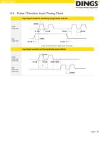
Signal Input Pulse / Direction Input Timing Chart Input signal waveform and timing (single pulse method) STEP Input port Input signal waveform and timing (double pulse method) STEP Input port (Forward) DIR Input port (Reverse)
Open the catalog to page 10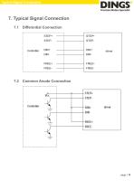
Typical Signal Connection 7. Typical Signal Connection 7.1 Differential Connection Common Anode Connection
Open the catalog to page 11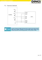
Typical Signal Connection Common Cathode The pulse, direction and offline terminals all have constant current input functions, which can be directly connected to the input signal without external series resistance step-down current-limiting protection. The VCC value is 3.5-26V.
Open the catalog to page 12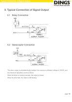
Typical Connection of Signal Output 8. Typical Connection of Signal Output 8.1 Relay Connection Optocoupler Connection The alarm output is photoelectrically isolated, the maximum withstand voltage is 30VDC, and the maximum saturation current is 50mA. When the driver is working normally, the output is closed. When the drive fails, the output is left floating.
Open the catalog to page 13
Wiring Requirements 9. Wiring Requirements 1) In order to prevent the driver from being interfered, it is recommended to use shielded cables for the control signal, and the shielding layer and the ground wire should be short-circuited. Except for special requirements, the shielding wire of the control signal cable should be grounded at one end: one end of the upper computer of the shielded wire is grounded, and the shielded wire One end of the drive is suspended. Only the same point is allowed to be grounded in the same machine. If it is not a real grounding wire, the interference may be...
Open the catalog to page 14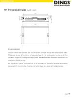
Installation Size 10. Installation Size (unit : mm) Drive installation Use the narrow side to install, and use M4 screws to install through the holes on both sides. The power device of the driver will generate heat. If it is continuously working under the condition of high input voltage and high power, the effective heat dissipation area should be enlarged or forced cooling. Do not use it in places where there is no air circulation or where the ambient temperature exceeds 40°C; do not install the drive in a humid place or a place with metal shavings.
Open the catalog to page 15
International Customer Person in Charge : Daniel Jang daniel@dingsmotion.com No. 2850 Luheng Road, Changzhou Economic Development Zone, Jiangsu Province, China +86-519-85177825, 85177826 North America Customer Person in Charge : Nicolas Ha sales@dingsmotionusa.com 335 Cochrane Circle Morgan Hill, CA 95037 +1-408-612-4970 China Customer +86-0519-8517 7825 +86-0519-8517 7807 No. 2850 Luheng Road, Changzhou Economic Development Zone, Jiangsu Province, China www.dingsmotion.com Sweet Shi info@dingsmotion.com No. 2850 Luheng Road, Changzhou Economic Development Zone, Jiangsu Province, China...
Open the catalog to page 16All Jiangsu DINGS' Intelligent Control Technology Co. catalogs and technical brochures
-
 General Catalog
295 Pages
-
 Simple Brochure
36 Pages
-
 DS-BVS-FETC-FCAO_Hardware Manual
18 Pages
-
 DS-BVS-BVM-Series_Reference Manual
181 Pages
-
 DINGS Servo Studio Manual
57 Pages
-
 DS-BVM-FETC-FCAO_Hardware Manual
15 Pages
-
 DS-OL42-ICAO_Technical Manual
53 Pages
-
 DS-CLS9-FETC-2I_Technical Manual
43 Pages
-
 DS-CLS9-FETC-2A_Technical Manual
43 Pages
-
 DS-CLS9-FETC_Technical Manual
17 Pages
-
 DS-CLS9-FCAO_Technical Manual
59 Pages
-
 DS-OLS10-FSC_Technical Manual
12 Pages
-
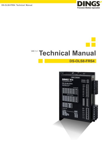 DS-OLS8-FRS4_Technical Manual
30 Pages
-
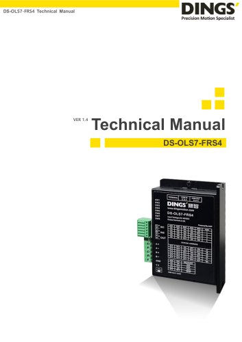 DS-OLS7-FRS4_Technical Manual
29 Pages
-
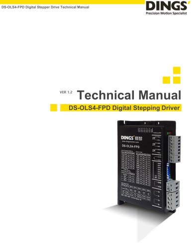 DS-OLS4-FPD_Technical Manual
17 Pages
-
 DS-OLS22_FPD_Technical Manual
16 Pages
-
 DS-OLS2-FPD_Technical Manual
16 Pages
-
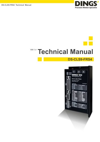 DS-CLS9-FRS4_Technical Manual
21 Pages
-
 DS-CLS9-FRS4-01_Technical Manual
29 Pages