Catalog excerpts

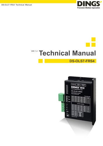
DS-OLS4-FPD Digital Stepper Drive Technical Manual Technical Manual DS-OLS4-FPD Digital Stepping Driver
Open the catalog to page 1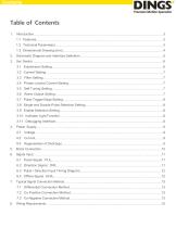
Schematic Diagram and Interface Definition………………………………………...……………….………5 Set Switch……………………………………………………………………………...………………..………6 3.1 Subdivision Setting…………………….………………………………………………………….………6 3.2 Current Setting.……..………………….………………………………………………………….………7 3.3 Filter Setting…………………………….…………………………………………………………………7 3.4 Phase Locked Current Setting………..…………………………………………………………………7 3.5 Self Tuning Setting……………………..…………………………………………………………………7 3.6 Alarm Output Setting……………………..………………………………………………………………7 3.7 Pulse Trigger Edge Setting……..……..………………..……………………………………………..…8 3.8 Single and Double Pulse Selection...
Open the catalog to page 2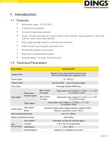
Input power supply : DC 24V~48V 8 speed current selection 16 levels of subdivision selection Single / Double pulse selection, phase-locked current selection, filtering selection, self tuning selection, alarm output logic selection Pulse triggering edge selection, enabling control selection PWM constant current bipolar subdivision drive Photoelectric isolation input function Motor short circuit protection function Exquisite design, low noise, and low vibration 1.2 Technical Parameters Drive model Adapter motor Adapted to two-phase hybrid stepping motor, DS-OLS4-FPD Maximum adaptation 4.2A...
Open the catalog to page 3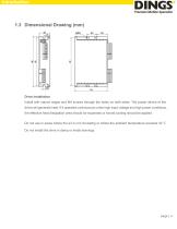
Drive installation Install with narrow edges and M4 screws through the holes on both sides. The power device of the driver will generate heat. If it operates continuously under high input voltage and high power conditions, the effective heat dissipation area should be expanded or forced cooling should be applied. Do not use in areas where the air is not circulating or where the ambient temperature exceeds 40 ℃ Do not install the drive in damp or metal shavings.
Open the catalog to page 4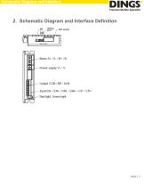
Schematic Diagram and Interface 2. Schematic Diagram and Interface Definition
Open the catalog to page 5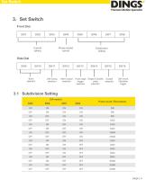
3. Set Switch Front Dial SW1 Phase-locked current Current setting Subdivision setting Band selection Self tuning selection Alarm output selection Pulse edge Single & Double Enable pulse trigger selection selection selection Self check Operation trigger 3.1 Subdivision Setting DIP switch SW8 Pulse count / Revolution
Open the catalog to page 6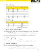
3.2 Current Setting DIP switch Phase current (peak) Filter setting 3.4 Phase Locked Current Setting SW4=off : (factory default) After the driver stops receiving pulses for about 0.4 seconds, the output current is 50% of the peak value (set to half current, which can reduce the heating of the driver and motor in some applications) SW4=on : The output current of the driver is 90% of the peak value when the motor is stationary. 3.5 Self Tuning Setting SW11=off : Motor power on self setting (factory default) SW11=on : The motor does not self adjust when powered on, and default parameters are...
Open the catalog to page 7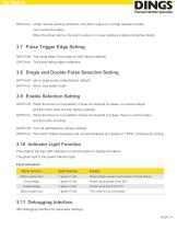
SW12=on : Under normal working conditions, the alarm output is in a high resistance state (non conductive state). When the driver alarms, the alarm output is in a low resistance state (conductive state). 3.7 Pulse Trigger Edge Setting SW13=off : The rising edge of the pulse is valid (factory default) SW13=on : The pulse falling edge is effective. 3.8 Single and Double Pulse Selection Setting SW14=off : set to single pulse mode (factory default) SW14=on : Set to dual pulse mode. 3.9 Enable Selection Setting SW15=off : When the driver is not enabled, it does not respond to pulses, no current...
Open the catalog to page 8
Power Supply 4. Power Supply 4.1 Voltage The chopper driver continuously changes the magnitude and direction of the motor winding terminal voltage during operation, while detecting the current to obtain accurate phase current. If both high efficiency and low noise are to be ensured, the driver supply voltage should be at least 5 times the rated phase voltage of the motor (the rated phase current of the motor × Phase resistance). If you need the motor to achieve better high-speed performance, you need to increase the driver supply voltage. If using a regulated power supply, it is required...
Open the catalog to page 9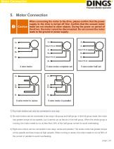
Motor Connection When connecting the motor to the drive, please confirm that the power supply to the drive is turned off first. Confirm that the unused motor Caution leads are not shorted to other objects. During the power on period of the driver, the motor cannot be disconnected. Do not connect the motor leads to the ground or power supply. 1) Four-wire motors can only be connected in one way. 2) Six-wire motors can be connected in two ways: full group and half group. In the full group mode, the motor has greater torque at low speeds, but it cannot run as fast as in the half group. When...
Open the catalog to page 10All Jiangsu DINGS' Intelligent Control Technology Co. catalogs and technical brochures
-
General Catalog
295 Pages
-
Simple Brochure
36 Pages
-
DS-BVS-FETC-FCAO_Hardware Manual
18 Pages
-
DS-BVS-BVM-Series_Reference Manual
181 Pages
-
DINGS Servo Studio Manual
57 Pages
-
DS-BVM-FETC-FCAO_Hardware Manual
15 Pages
-
DS-OL42-ICAO_Technical Manual
53 Pages
-
DS-CLS9-FETC-2I_Technical Manual
43 Pages
-
DS-CLS9-FETC-2A_Technical Manual
43 Pages
-
DS-CLS9-FETC_Technical Manual
17 Pages
-
DS-CLS9-FCAO_Technical Manual
59 Pages
-
DS-OLS10-FSC_Technical Manual
12 Pages
-
DS-OLS8-FRS4_Technical Manual
30 Pages
-
DS-OLS7-FRS4_Technical Manual
29 Pages
-
DS-OLS8-FPD_Technical Manual
16 Pages
-
DS-OLS22_FPD_Technical Manual
16 Pages
-
DS-OLS2-FPD_Technical Manual
16 Pages
-
DS-CLS9-FRS4_Technical Manual
21 Pages
-
DS-CLS9-FRS4-01_Technical Manual
29 Pages


