Catalog excerpts
Table of Contents 1. Features ……………………………………………………………………………3 2. Technical Parameters…………………………………………………………………3 3. Schematic and Interface Definition………………………………………………4 4. Setting Switch………………………………………………………………………….5 5. Power Supply…………………………..…………………
Open the catalog to page 2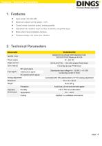
Features / Technical Parameters Maximum output current (peak) : 4.5A Control mode: constant speed, analog quantity Optoelectronic isolation input function, 5-24VDC compatible input Motor short circuit protection function Compact design, low noise, low vibration 2. Technical Parameters Drive model Applied motor Adapted to two-phase hybrid stepping motor, DS-OLS10-FSC Maximum fit 4.5A Power supply Output current DS-OLS10-FSC:1.0A-4.5A/ phase (Peak Value) Drive method Full-bridge bi-polar PWM driver IN1 (start) signal Input signal In2(direction) signal IN3 (speed switch) signal Analog...
Open the catalog to page 3
Schematic and Interface Definition 3. Schematic and Interface Definition Motor and Power Supply Signal Input/output Analog input Indicator light 1. Motor connection and power input (arranged from left to right as shown in the diagram) Pin1 --V+, Pin2 --V-, Pin3 --A+, Pin4 --A -, Pin 5 --B+, Pin 6 --B – 2. Signal input (arranged from left to right as shown in the diagram) Pulse control mode: Pin1--COM, Pin2--IN1(start), Pin3-- IN2 (direction), Pin4-- IN3 (speed switch) 3. Analog input (arranged from left to right according to the diagram) Pin 1--AIN+, Pin 2--IN, Pin 3--AINA. Connect 10K...
Open the catalog to page 4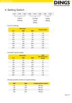
Setting Switch Current settings DIP switch Phase Current Constant speed setting SW4 Analog quantity maximum speed setting SW7 Analog maximum speed
Open the catalog to page 5
Setting Switch Model specification Analog speed regulation mode: according to the potentiometer input speed regulation, IO control the start, stop, running direction and switching speed (switching: the speed fixed by the general dialing of the optocoupler guide, and the speed controlled by the analogue of the optocoupler cutoff) Indicator function This product has two red and green LED indicator to show the status: Indicator status Green Light flashing Drive is working properly Overvoltage power input The supply voltage is greater than 48VDC Driver overcurrent Short circuit of motor winding...
Open the catalog to page 6
Power Supply 5. Power Supply Voltage When the chopper driver works, it constantly changes the size and direction of the voltage at the end of the motor winding and detects the current to obtain the accurate phase current. If both high efficiency and low noise are to be ensured, the power supply voltage of the driver shall be at least 5 times the rated phase voltage of the motor (i.e., the rated phase current of the motor × phase resistance). If you need the motor for better high-speed performance, you need to increase the drive supply voltage. If a regulated power supply is used, the...
Open the catalog to page 7
Motor Connection 6. Motor Connection Warning Before connecting the motor to the driver, make sure the power is turned off. Verify that unused motor leads are not short-circuited with other objects. Do not disconnect the motor while the drive is energized. Do not connect the motor lead to the ground or to the power supply. 1) The four-wire motor can only be connected in one way. 2) The six-wire motor can be connected in two ways: full group and half group. In full assembly mode, the motor has more torque at low speeds, but cannot run as fast as in half assembly. For full group operation, the...
Open the catalog to page 8
Typical Connection Signal 7. Typical Connection Signal Common anode connection Common cathode connection
Open the catalog to page 9
Wiring Requirements 8. Wiring Requirements 1) In order to prevent the interference of the driver, it is recommended to use the shielded cable for the control signal, and the shielding layer is short connected with the ground wire. Except for special requirements, the shielded wire of the control signal cable is single-ended grounded: the upper computer end of the shielded wire is grounded, and the driver end of the shielded wire is suspended. It is only allowed to be grounded at the same point in the same machine. If it is not the real grounding wire, the interference may be serious. At...
Open the catalog to page 10
Drive installation Install with narrow sides, using M4 screws through holes on both sides. The power components of the driver will heat up. If the driver works continuously under the condition of high input voltage and large power, the effective heat dissipation area should be expanded or forced cooling. Do not use it in places where the air is not circulating or where the ambient temperature exceeds 40℃. Do not install the drive in damp or metal shavings.
Open the catalog to page 11
International Customer Person in Charge : Daniel Jang daniel@dingsmotion.com No. 2850 Luheng Road, Changzhou Economic Development Zone, Jiangsu Province, China +86-519-85177825, 85177826 North America Customer Person in Charge : Nicolas Ha sales@dingsmotionusa.com 335 Cochrane Circle Morgan Hill, CA 95037 +1-408-612-4970 China +86-0519-8517 7825 +86-0519-8517 7807 Customer Person in Charge : No. 2850 Luheng Road, Changzhou Economic No. 2850 Luheng Road, Changzhou Development Zone, Jiangsu Province, China Economic Development Zone, Jiangsu Province, China It is prohibited to copyright or...
Open the catalog to page 12All Jiangsu DINGS' Intelligent Control Technology Co. catalogs and technical brochures
-
 General Catalog
295 Pages
-
 Simple Brochure
36 Pages
-
 DS-BVS-FETC-FCAO_Hardware Manual
18 Pages
-
 DS-BVS-BVM-Series_Reference Manual
181 Pages
-
 DINGS Servo Studio Manual
57 Pages
-
 DS-BVM-FETC-FCAO_Hardware Manual
15 Pages
-
 DS-OL42-ICAO_Technical Manual
53 Pages
-
 DS-CLS9-FETC-2I_Technical Manual
43 Pages
-
 DS-CLS9-FETC-2A_Technical Manual
43 Pages
-
 DS-CLS9-FETC_Technical Manual
17 Pages
-
 DS-CLS9-FCAO_Technical Manual
59 Pages
-
 DS-OLS8-FRS4_Technical Manual
30 Pages
-
 DS-OLS7-FRS4_Technical Manual
29 Pages
-
 DS-OLS8-FPD_Technical Manual
16 Pages
-
 DS-OLS4-FPD_Technical Manual
17 Pages
-
 DS-OLS22_FPD_Technical Manual
16 Pages
-
 DS-OLS2-FPD_Technical Manual
16 Pages
-
 DS-CLS9-FRS4_Technical Manual
21 Pages
-
 DS-CLS9-FRS4-01_Technical Manual
29 Pages