Catalog excerpts

Click to return to table of contents Connection Diagram of Motor and Driver……………..……………………..5 Motor Operate / Stop Control (EN)…..………………………………...6 Motor Rotation Direction Control (F/R).………
Open the catalog to page 2
Specification and Description / Product Characteristic This closed-loop speed controller is designed with the latest type IGBT and MOS power devices. It takes advantage of DC brushless motor’s Hall signal to double frequency for closed-loop speed control. PID control links with the speed controller. The control system is stable and reliable, especially at low speed, it always can reach the maximum torque, The speed control range is from 150 to 20000rpm. PID speed, current double loop regulator Electrical stop to ensure the quick action Over load ratio larger than 2, the torque can always...
Open the catalog to page 3
Terminal Connection Hall signal A phase input Hall signal B phase input Hall signal C phase input Hall signal power line Terminal Name CW/CCW terminal Stop/Start terminal Brake terminal Analog signal input terminal Speed output terminal Alarm output terminal +5V power output terminal Signal ground Built-in potentiometer R-SI : Adjust the motor speed gain, which can be adjusted from 0~100%. Built-in potentiometer R-CS : Maximum protection current setting, built-in potentiometer can be set 0%~100% continuous current protection.
Open the catalog to page 4
Connection Diagram of motor and driver / Dimension 4. Connection Diagram of motor and driver
Open the catalog to page 5
Speed Adjustment Method This driver provides the user below three-speed control method: Inner potentiometer speed adjustment : Rotate the potentiometer on the driver panel counterclockwise, the rotate speed decrease, rotate the potentiometer on the driver panel clockwise, the rotate speed becomes higher. Please make sure the potentiometer is set in the minimum state when you use external input mode to adjust the speed. External input adjustment : Connect the terminals of the external potentiometer to the GND and +6.25v terminal, connect the regulator terminal to SV, then you can adjust the...
Open the catalog to page 6
Functions and Usage / Communication Method Brake the Motor to Stop (BK) You can break the motor to stop if need. The motor will run when the terminal “BK” not connects to “GND”, but if you connect these two terminals, the motor will stop quickly. And the motor stopping time will be decided by inertia and load adding on the motor. If you are not necessary to stop the motor quickly, please DO NOT use this function, cause it has some electrical and mechanical impact on the motor and driver. Speed Signal Output (PG) The speed pulse output port is 0C, output 30V/10mA max. You can connect with a...
Open the catalog to page 7
Communication Method support multiple communication rates (see parameter table for details). If the communication mode control motor is required, it must be performed under the MBUS control mode and the internal control terminal. Function parameters support 03H multi-register read, 06H single register write. Site Address: 00 : Broadcast Address 1-250 : User Address 251-255 : Special address, user cannot use No. First byte : control bit state Setting range First byte: Bit5:X12 Bit6:KH Second byte : Hall angle and motor poles Second byte: Maximum speed in analog adjustment First byte: start...
Open the catalog to page 8
Communication Method First byte: site address Second byte: reserve 10-17 Real speed First byte: bus voltage Second byte: bus current First byte: reserved reserve Second: reserved First byte: fault status Second byte: reserved 00: No Alarm 01: Motor Blocked (shaft stuck) 02: Overload 03: Motor hall fault (hall wire disconnected or damaged) 04: Low supply voltage 08: High supply voltage 20: Large instantaneous motor current (sudden motor load increase or motor phase circuit short) reserve Site address 8000H-8017H Read-write register Site address 8018H-801FH Read-only register Other address is...
Open the catalog to page 9
Communication Wiring Method External SW speed mode 1 External SW speed mode 2 KH: 0: Speed closed loop mode Function External simulation speed Internal communication control 1: Speed open loop mode 8. Communication Wiring Method RS-485 communication can be communicated by driving a conventional 3-pin 2.54 wiring port. The pins for a conventional 3-pin 2.54 wiring port are defined as follows:
Open the catalog to page 10
International Customer Person in Charge : Daniel Jang daniel@dingsmotion.com Building 1#, 355 Longjin Road, Changzhou Economic Development Zone, Jiangsu, China +86-519-85177826, 85177827 North America Customer Person in Charge : Nicolas Ha sales@dingsmotionusa.com 335 Cochrane Circle Morgan Hill, CA 95037 +1-408-612-4970 China Customer Person in Charge : info@dingsmotion.com Building 1#, 355 Longjin Road, Economic Development Zone, Jiangsu, China www.dingsmotion.com Changzhou Economic Development Zone, Jiangsu, China +86-519-85177826, 85177827 It is prohibited to copyright or replication of...
Open the catalog to page 11All Jiangsu DINGS' Intelligent Control Technology Co. catalogs and technical brochures
-
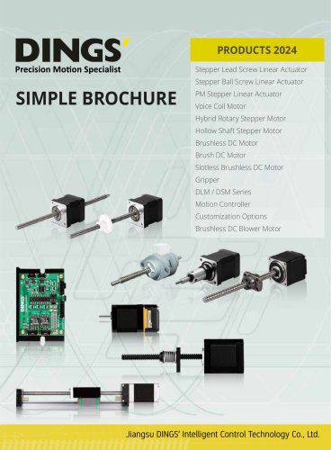 Simple Brochure
36 Pages
-
 General Catalog
288 Pages
-
 DS-CLS9-FRS4-01_Technical Manual
34 Pages
-
 DS-CLS9-FRS4_Technical Manual
26 Pages
-
 DS-OLS2-FPD_Technical Manual
19 Pages
-
 DS-OLS22_FPD_Technical Manual
16 Pages
-
 DS-OLS4-FPD_Technical Manual
23 Pages
-
 DS-OLS8-FPD_Technical Manual
16 Pages
-
 DS-OLS7-FRS4_Technical Manual
30 Pages
-
 DS-OLS8-FRS4_Technical Manual
32 Pages
-
 DS-OLS10-FSC_Technical Manual
12 Pages
-
 DS-CLS9-FCAO_Technical Manual
62 Pages
-
 DS-CLS9-FETC_Technical Manual
19 Pages
-
 DS-CLS9-FETC-2A_Technical Manual
43 Pages
-
 DS-CLS9-FETC-2I_Technical Manual
43 Pages
-
 DS-OL42-ICAO_Technical Manual
57 Pages
-
 DS-OLBS2-FRS4_Technical Manual
11 Pages
-
 DS-OLBS8-FRS4_Technical Manual
15 Pages
-
 DS-BVM-FETC-FCAO_Hardware Manual
15 Pages
-
 DINGS Servo Studio Manual
58 Pages
-
 DS-BVS-BVM-Series_Reference Manual
181 Pages
-
 DS-BVS-FETC-FCAO_Hardware Manual
18 Pages