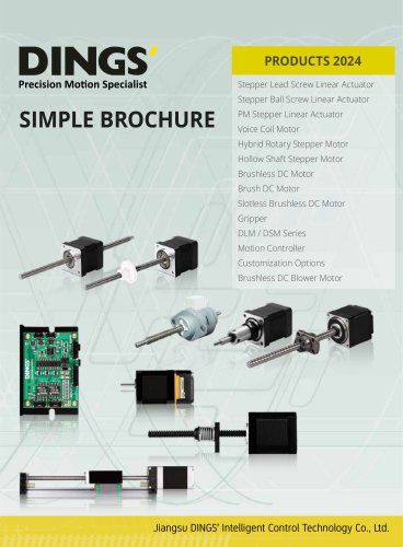
Catalog excerpts
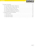
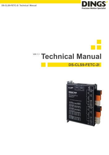
10. Control Parameter……………………………………………………………………14 10.1 Controller Basic Status (Class 01)………………………………………….14 10.2 Basic Parameter Setting (Class 02)………………………………………….14 10.3 Control Parameters (Class 05)………………………………………………..15 10.4 Input Block Designation (Class 06)……………………………………………16 10.5 Output Block Specification (Class 07)…………………………………………18 11.
Open the catalog to page 3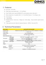
Output rated current (peak value) :0.5~3.0A/Phase Pulse, RS485 control, support MODBUS RTU communication protocol, Max site 31 Hollow integral drive, Compatible with E, C, K, N and Shaft Diameter<11mm Stepper motor Protection function : Current over, Voltage over , Under voltage, Power protection against reverse 2 High speed input ports, Maximum response frequency:500KHz(Duty ratio 50%) 2. Technical Parameters Drive model Adapted motor Suitable for two-phase hybrid stepping motor, the maximum adaptation is 3.0A(peak) Power supply Output current 0.5A~3.0A/phase (peak) Full-bridge bipolar PWM...
Open the catalog to page 4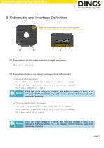
Schematic and Interface Definition 3. Schematic and Interface Definition This screw head can be used in earth (ground) P1. Power input (in the order from left to right as shown) Pin 1 ---V+ P2. Signal input/output (as shown, arranged from left to right) (1) DS-OL42-IPD Pulse control : Pin 1--- STEP+, Pin 2---STEP-, Pin 3---DIR+, Pin 4--- DIR-, Pin 5--- COMIN, Pin 6 --- IN3, Pin 7 --- IN4, Pin 8 --- OUT+, Pin 9 --- OUT-, Pin 10 --- 485GND, Pin 11 feet --- 485-A, Pin 12 --- 485-B STEP, DIR input voltage is 5~24Vdc, IN1, IN2 input voltage is 5Vdc, if the voltage is 12Vdc or 24Vdc, 1K, 2.2K...
Open the catalog to page 5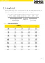
Setting Switch 4. Setting Switch (The DIP switch function can be via communication : on / off ; after the DIP switch is disabled, the subdivision, current, and pulse mode parameters are set via communication) Resolution Setting DIP Switch
Open the catalog to page 6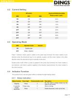
Setting Switch Current Setting DIP switch Operation mode Double pulse Operating Mode Pulse + direction mode: pulse is added to the pulse input terminal, the motor rotates in one direction when the directional input is not optically coupled, and the motor rotates in the other direction when the directional input is optically conductive Double pulse mode: When a pulse is applied to the pulse input terminal, the motor rotates in one direction, and when a pulse is applied to the direction input terminal, the motor rotates in the other direction Indicator Function This product has 2 red and...
Open the catalog to page 7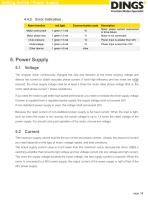
Setting Switch / Power Supply 4.4.2 Error Indication : Alarm function Communication code Motor overcurrent Motor phase loss Description Motor phase current overcurrent or drive failure Motor is not connected Over pressure Power input is greater than 42V Power input is less than 18V Other alarms Power Supply The chopper driver continuously changes the size and direction of the motor winding voltage and detects the current to obtain accurate phase current. If both high efficiency and low noise are to be ensured, the driver supply voltage shall be at least 5 times the motor rated phase voltage...
Open the catalog to page 8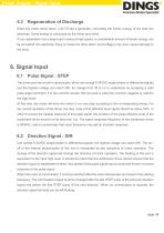
Power Supply / Signal Input When the motor slows down, it ACTS like a generator, converting the kinetic energy of the load into electricity. Some energy is consumed by the driver and motor. If your application has a large load running at high speed, a considerable amount of kinetic energy can be converted into electricity. Easy to cause the drive alarm (overvoltage) may even cause damage to the drive. Pulse Signal : STEP The driver port has a built-in optocoupler, which can accept 5-24VDC single-ended or differential signals, and the highest voltage can reach 26V. Its change from off to on...
Open the catalog to page 9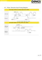
Signal Input Pulse / Direction Input Timing Diagram Input signal waveform and timing (single pulse method) STEP Input Input signal waveform and timing (double pulse method) STEP Input (Forward)
Open the catalog to page 10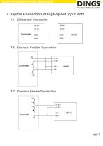
Typical Connection of High-Speed Input 7. Typical Connection of High-Speed Input Port 7.1 Differential Connection Common Positive Connection Common Female Connection
Open the catalog to page 11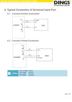
Typical Connection of Universal Input 8. Typical Connection of Universal Input Port 8.1 Common Positive Connection Common Female Connection
Open the catalog to page 12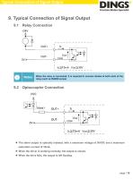
Typical Connection of Signal Output 9. Typical Connection of Signal Output 9.1 Relay Connection When the relay is connected, it is required to connect diodes at both ends of the relay (such as IN4000 series) Optocoupler Connection The alarm output is optically isolated, with a maximum voltage of 30VDC and a maximum saturation current of 10mA. When the driver is working normally, the output is closed. When the drive fails, the output is left floating.
Open the catalog to page 13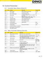
Control Parameter Controller Basic Status (Class 01) word Range / unit Motor current Motor real-time current value Input voltage Current input voltage Pulse mode error code Operating status Set segmentation value 1 is pulse + direction mode, 2 is double pulse mode Code at the time of alarm, see 1-2 for content, and display "0" for no fault Drive running status, see 1-1 hardware version Drive hardware version Software version Drive software version current position target location Actual speed display Actual location IO select multiple run paragraphs Multi-segment writing error No...
Open the catalog to page 14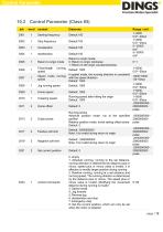
Control Parameter Control Parameter (Class 05) Starting frequency Stop frequency Return to origin mode Fixed-length speed Return to origin mode, 0: Return to origin clockwise 1: Return to the origin counterclockwise Speed mode running speed In speed mode, the running direction is consistent with the speed direction Default: 1000 Home speed Creeping speed Running speed after hitting the origin Default: 1000 Home offset Output pulse Running stroke Absolute position mode: run to the specified position Relative position mode: travel setting offset stroke Default: 0 Positive soft limit Default:...
Open the catalog to page 15All Jiangsu DINGS' Intelligent Control Technology Co. catalogs and technical brochures
-
 General Catalog
295 Pages
-
 Simple Brochure
36 Pages
-
 DS-BVS-FETC-FCAO_Hardware Manual
18 Pages
-
 DS-BVS-BVM-Series_Reference Manual
181 Pages
-
 DINGS Servo Studio Manual
57 Pages
-
 DS-BVM-FETC-FCAO_Hardware Manual
15 Pages
-
 DS-OL42-ICAO_Technical Manual
53 Pages
-
 DS-CLS9-FETC-2I_Technical Manual
43 Pages
-
 DS-CLS9-FETC-2A_Technical Manual
43 Pages
-
 DS-CLS9-FETC_Technical Manual
17 Pages
-
 DS-CLS9-FCAO_Technical Manual
59 Pages
-
 DS-OLS10-FSC_Technical Manual
12 Pages
-
 DS-OLS8-FRS4_Technical Manual
30 Pages
-
 DS-OLS7-FRS4_Technical Manual
29 Pages
-
 DS-OLS8-FPD_Technical Manual
16 Pages
-
 DS-OLS4-FPD_Technical Manual
17 Pages
-
 DS-OLS22_FPD_Technical Manual
16 Pages
-
 DS-OLS2-FPD_Technical Manual
16 Pages
-
 DS-CLS9-FRS4_Technical Manual
21 Pages
-
 DS-CLS9-FRS4-01_Technical Manual
29 Pages