Catalog excerpts
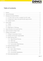
Schematic and Interface Definition…………………………………….…………………………5 3.1 P1 Power Input (as shown, arranged from left to right)……..…………………….5 3.2 P2 Signal Input / output (in the order from left to right as shown)…...………..…………5 3.3 Indicator Function……………………………………………...……………………………5 Typical Connection of Universal Input Port……………………………………………….…….7 Typical Connection of Signal Output…………………………………………………………….8 CANopen Communication………………………………………………………………………...9 7.1 CANopen Communication Service………………………………………………………9 7.2 CANo
Open the catalog to page 2
7.7 Process Data Object (PDO) ………………………………………………………………18 7.7.1 Transmission Framework and features of PDO………………………………...18 7.7.2 The PDO Object…………………………………………………………………20 7.7.3 Communication Parameters of PDO…………………………………………….20 7.7.4 PDO Mapping Parameters……………………………………………………….23 7.8 Synchronization Object (SYNC) …………………………………………………………23 7.8.1 Sync Generator……………………………………………………………………24 7.8.2 Transmission Framework for Synchronous Objects…………………………..24 7.9 Emergency Target Service (EMCY) ……………………………………………………..25 8.
Open the catalog to page 3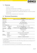
Features / Technical Parameters Output rated current (peak value): 0.5~3.0A/phase Support CANopen communication protocol,Support control mode PP, PV, HM Through hole type of Integrated Driver compatible DINGS' NEMA Size 17 step motor is diameter less than 11mm. - Input and Output is 4 general input and 1 universal output 2. Technical Parameters Drive model DS-OL42-ICAO Suitable for two-phase hybrid stepping motor, the maximum adaptation is 3.0A (peak) Adapted motor Power supply Output current 0.5A~3.0A/phase (peak) Full-bridge bipolar PWM drive Drive way Device initialization time Input...
Open the catalog to page 4
Schematic and Interface Definition 3. Schematic and Interface Definition P1 Power Input (as shown, arranged from left to right) Pin 1 ---V+、Pin 2 ---V-、 P2 Signal Input / Output (in the order from left to right as shown) Pin 1--- RS485+, Pin 2--- RS485-, Pin 3--- IN1, Pin 4--- IN2, Pin 5--- COMIN, Pin 6 --- IN3, Pin 7 --- IN4, Pin 8 --- OUT+, Pin 9 --- OUT-, Pin 10 --- CANGND, Pin 11 --- CANL, Pin 12 --- CANH Indicator Function This product has 2 red and green LEDs to indicate the light display status: Status indication: Status function Green light Communication code On, the motor is phase...
Open the catalog to page 5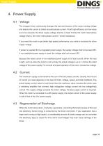
Power Supply Voltage The chopper driver continuously changes the size and direction of the motor winding voltage and detects the current to obtain accurate phase current. If both high efficiency and low noise are to be ensured, the driver supply voltage shall be at least 5 times the motor rated phase voltage (that is, the motor rated phase current × phase resistance). If you need the motor to get better high speed performance, you need to increase the driver supply voltage. If power is supplied from a regulated power supply, the supply voltage shall not exceed 36V. If non-stabilized power...
Open the catalog to page 6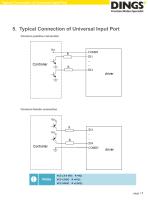
Typical Connection of Universal Input Port 5. Typical Connection of Universal Input Port Common positive connection Common female connection
Open the catalog to page 7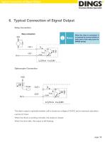
Typical Connection of Signal Output 6. Typical Connection of Signal Output Relay Connection When the relay is connected, it is required to connect diodes at both ends of the relay (such as IN4000 series) Optocoupler Connection The alarm output is optically isolated, with a maximum voltage of 30VDC and a maximum saturation current of 10mA. When the driver is working normally, the output is closed. When the drive fails, the output is left floating.
Open the catalog to page 8
CANopen Communication CANopen Communication Service CANopen specifications followed by the product: ● Follow standards CAN2.0A ● Compliance with CANopen Standard Agreement DS301V4.02 ● Compliance with CANopen Standard Agreement DSP402V2.01 Services supported by the CANopen driver: ● Support NMT Slave service ● Device monitoring: support heartbeat packets and node protection ● Support for PDO services: each slave station can be configured with up to 4 TXPDos and 4 RXPdos ● PDO transport types: event trigger, time trigger, synchronous cycle, synchronous noncycle ● Support for SDO services ●...
Open the catalog to page 9All Jiangsu DINGS' Intelligent Control Technology Co. catalogs and technical brochures
-
 General Catalog
295 Pages
-
 Simple Brochure
36 Pages
-
 DS-BVS-FETC-FCAO_Hardware Manual
18 Pages
-
 DS-BVS-BVM-Series_Reference Manual
181 Pages
-
 DINGS Servo Studio Manual
57 Pages
-
 DS-BVM-FETC-FCAO_Hardware Manual
15 Pages
-
 DS-CLS9-FETC-2I_Technical Manual
43 Pages
-
 DS-CLS9-FETC-2A_Technical Manual
43 Pages
-
 DS-CLS9-FETC_Technical Manual
17 Pages
-
 DS-CLS9-FCAO_Technical Manual
59 Pages
-
 DS-OLS10-FSC_Technical Manual
12 Pages
-
 DS-OLS8-FRS4_Technical Manual
30 Pages
-
 DS-OLS7-FRS4_Technical Manual
29 Pages
-
 DS-OLS8-FPD_Technical Manual
16 Pages
-
 DS-OLS4-FPD_Technical Manual
17 Pages
-
 DS-OLS22_FPD_Technical Manual
16 Pages
-
 DS-OLS2-FPD_Technical Manual
16 Pages
-
 DS-CLS9-FRS4_Technical Manual
21 Pages
-
 DS-CLS9-FRS4-01_Technical Manual
29 Pages