Catalog excerpts

MODBUS-RTU Protocol Convention MODBUS-RTU Protocol Convention
Open the catalog to page 1
Table of Contents 1. Modbus-RTU Protocol Example.…………………..………….….…………..3 1.1 Running Motor……….………………………...………………………..3 1.1.1 Absolute Position Mode………………………………………..3 1.1.2 Relative Position Mode……………..………..……………………..5 Read Alarm Status…………….…………………………….…………..9 1.3.1 Alarm Status…..……………………………………………………..9
Open the catalog to page 2
Modbus-RTU Protocol Example 1. Modbus-RTU Example 1.1 Running Motor 1.1.1 Absolute Position Mode Step Add. Running Speed Target Position Control Command Example. 1 Step 1 : Set Speed Write Single Register Running Speed Starting Address Starting Address
Open the catalog to page 3
Modbus-RTU Protocol Example Example. 2 Step 2 : Set Position Write Multi Register Target Position Quantity of Registers 5000 pulse -5000 pulse Data Request Slave ID Starting Address Byte Count Starting Address Example. 3 Step 3 : Command Run Write Single Register Starting Address Starting Address
Open the catalog to page 4
Modbus-RTU Protocol Example Relative Position Mode Step Add. Running Speed Running Stroke Control Command Example. 1 Step 1 : Set Speed Write Single Register Running Speed Starting Address Starting Address
Open the catalog to page 5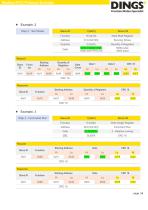
Modbus-RTU Protocol Example Example. 2 Step 2 : Set Stroke Write Multi Register Running Stroke Quantity of Registers 5000 pulse -5000 pulse Data Request Slave ID Starting Address Byte Count Starting Address Example. 3 Step 3 : Command Run Write Single Register Starting Address Starting Address
Open the catalog to page 6
Modbus-RTU Protocol Example 1.2 Read Motor Status 1.2.1 Read Current Position Step Add. Current Position Unit pulse Step 1 : Read Position Example Step 1 : Read Current Position Read Register Current Position Starting Address Byte Count
Open the catalog to page 7
Modbus-RTU Protocol Example Read Current Speed Step Add. Current Speed Step 1 : Read Speed Example Step 1 : Read Current Speed Read Register Current Speed Starting Address Byte Count
Open the catalog to page 8
Modbus-RTU Protocol Example Read Alarm Status Alarm Status Step Add. Alarm Status Step 1 : Read Alarm Example Step 1 : Read Alarm Status Read Register Alarm Status Starting Address IF : alarm status = 11 ( 0 x 000B ) = Motor phase loss Byte Count
Open the catalog to page 9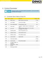
Control Parameter 2. Control Parameter Notes Informal version of communication parameters, some parameters are fixed and not open. 2.1 Controller Basic Status (Class 01) adr Motor current Motor real-time current value Input voltage Current input voltage Pulse mode 1 is pulse + direction mode, 2 is double pulse mode error code Code at the time of alarm, see 1-2 for content, and display "0" for no fault Operating status Drive running status, see 1-1 hardware version Drive hardware version Software version Drive software version current position target location Actual speed display Actual...
Open the catalog to page 10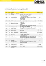
Control Parameter 2.2 Basic Parameter Setting (Class 02) adr Motor switching Elaborate direction Range / unit Select the motor running direction User instructions Set when the motor is stopped 1: user parameter reset 2: Clear the alarm (except for some hardware failure alarms) 3: drive restart Half-flow ratio Stop current ratio (effective in open loop mode) Motor control mode 0: open loop 1: closed loop Default: 1 Angular filtering The smaller the value, the smoother the motor runs, but the higher the delay Digital filtering Filter coefficient of input pulse. The larger the value, the lower...
Open the catalog to page 11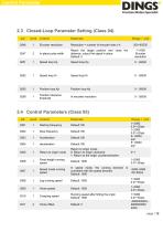
Control Parameter 2.3 Closed-Loop Parameter Setting (Class 04) adr Range / unit Encoder resolution Resolution = number of encoder lines x 4 In-place pulse width Reach the target position and close the distance, output the signal in place Default: 0 Position tolerance threshold 2.4 Control Parameters (Class 05) adr Starting frequency Stop frequency Return to origin mode Return to origin mode, 0: Return to origin clockwise 1: Return to the origin counterclockwise Fixed-length running speed Speed mode running speed In speed mode, the running direction is consistent with the speed direction...
Open the catalog to page 12
Control Parameter Output pulse Running stroke Absolute position mode: run to the specified position Relative position mode: travel setting offset stroke Default: 0 Positive soft limit Default: 2000000000 Note: It is invalid during return to origin Negative soft limit Default: -2000000000 Note: It is invalid during return to origin control commands 0: empty 1. Absolute running, running to the set distance, running direction is determined by distance plus or minus, speed plus or minus value is invalid, it is effective to modify target position during running 2. Relative running, running at a...
Open the catalog to page 13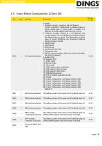
Control Parameter 2.5 Input Block Designation (Class 06) adr Range / unit 0: empty 1. Absolute running, running to the set distance, running direction is determined by distance plus or minus, speed plus or minus value is invalid, it is effective to modify target position during running 2. Relative running, running at a set distance and running speed. The running direction is determined by the distance plus or minus. The speed plus or minus value is invalid. Modifying the movement distance during running is invalid 3. Speed mode 4. Jog forward 5. Reverse jog 6. deceleration and stop 7....
Open the catalog to page 14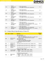
Control Parameter 0: OFF (initial value 0) 1: ON (trigger the action of IN1 configuration) 0: OFF (initial value 0) 1: ON (trigger the action of IN2 configuration) 0: OFF (initial value 0) 1: ON (trigger the action of IN3 configuration) 0: OFF (initial value 0) 1: ON (trigger the action of IN4 configuration) 0: OFF (initial value 0) 1: ON (trigger the action of IN5 configuration) 0: OFF (initial value 0) 1: ON (triggers the action configured by IN6) (During external pulse, the function of the pseudo communication port is disabled) 0: OFF (initial value 0) 1: ON (trigger the action of IN7...
Open the catalog to page 15All Jiangsu DINGS' Intelligent Control Technology Co. catalogs and technical brochures
-
 General Catalog
295 Pages
-
 Simple Brochure
36 Pages
-
 DS-BVS-FETC-FCAO_Hardware Manual
18 Pages
-
 DS-BVS-BVM-Series_Reference Manual
181 Pages
-
 DINGS Servo Studio Manual
57 Pages
-
 DS-BVM-FETC-FCAO_Hardware Manual
15 Pages
-
 DS-OL42-ICAO_Technical Manual
53 Pages
-
 DS-CLS9-FETC-2I_Technical Manual
43 Pages
-
 DS-CLS9-FETC-2A_Technical Manual
43 Pages
-
 DS-CLS9-FETC_Technical Manual
17 Pages
-
 DS-CLS9-FCAO_Technical Manual
59 Pages
-
 DS-OLS10-FSC_Technical Manual
12 Pages
-
 DS-OLS8-FRS4_Technical Manual
30 Pages
-
 DS-OLS7-FRS4_Technical Manual
29 Pages
-
 DS-OLS8-FPD_Technical Manual
16 Pages
-
 DS-OLS4-FPD_Technical Manual
17 Pages
-
 DS-OLS22_FPD_Technical Manual
16 Pages
-
 DS-OLS2-FPD_Technical Manual
16 Pages
-
 DS-CLS9-FRS4_Technical Manual
21 Pages
-
 DS-CLS9-FRS4-01_Technical Manual
29 Pages