Catalog excerpts
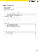
Sensor, Digital Input Circuit (Contact)……………………………………………………………..7 Sensor, Digital Input Circuit (Collector Output)………………………………………………….7 Output Circuit Diagram…………………………………………...…………………………..……………7 5.1 Digital Output Circuit (Relay Connection)………………………………………….……..……7 5.2 Digital Output Circuit (Opto-Coupler Connection)………………………………..……………….8 5.3 Differential Output Circuit (Encoder Output)……….………………………….…………………8 Pulse & Direction Input Sequence Diagram………………...…………………………………..…………9 Indicator Light………………………………………………………….…………………………..………10
Open the catalog to page 2
Main Specification 1. Main Specification Project power supply Rated output current Maximum output current Control object motor Drive mode PWM constant current drive [Input] ・ Pulse, direction input (configurable as digital input) ・ Digital input 5 ・ Encoder input (A, B, Z) [Output] ・ 4 digital outputs ・ Coded signal output (differential A, B, Z) Digital input details /SV ON (Servo On) /RESET (alarm reset) /START (motor start/stop) /JOG (motor jog) /HOME (zero point) Digital output details Status, fault Continuous current Instantaneous current The rest of the input/output can be freely...
Open the catalog to page 3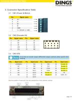
Connector Specification Table 3. Connector Specification Table 3.1 CN1 (Power & Motor) Pin Signal name Signal name Signal name 18-23 feet are encoder output {differential output}, optional, please specify when ordering Signal name Signal name Signal name Signal name See the position of each pin from the perspective of the insertion surface
Open the catalog to page 5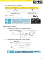
Connector Specification Table / Input Circuit Diagram Signal name Signal name Standard : RJ45 Type × 2 See the position of each pin in a face-to-face view When using multiple serial connections, the terminal resistance is the short-circuit when the last CN5 pins 3 and 8 are short-circuited, and the 6-pin and 7-pin are short-circuited. Remark : CN4 does not contain terminating resistor 4. Input Circuit Diagram 4.1 Command Pulse Input Circuit (Differential Drive) 4.2 Command Pulse Input Circuit (Open Collector) This product is compatible with +5V/+24V Signal and it does not need current limit...
Open the catalog to page 6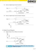
Input Circuit Diagram / Output Circuit Diagram 4.3 Sensor, Digital Input Circuit (Contact) 4.4 Sensor, Digital Input Circuit (Collector Output) 5. Output Circuit Diagram 5.1 Digital Output Circuit (Relay Connection) When connects relay, diodes at both ends of relay (similar to IN4007) are required. page│7
Open the catalog to page 7
Output Circuit Diagram 5.2 Digital Output Circuit (Opto-Coupler Connection) 5.3 Differential Output Circuit (Encoder Output) There is no opto-coupler isolation for encoder output. Before power on, please confirm whether the wiring is correct and Caution there is short circuit. So as to avoid any damaging the upper computer and driver by introducing the 24V power supply on the CN3 port.
Open the catalog to page 8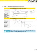
Pulse & Direction Input Sequence Diagram / Indicator Light 6. Pulse & Direction Input Sequence Diagram Input Signal Waveform and Timing (1 Pulse Mode) STEP Input Port DIR Input Port (Low Level forward rotation, High level reverse rotation) Input Signal Waveform and Timing (2 Pulse Mode) STEP Input Port (pulse Input Forward) DIR Input Port (Pulse Input Backward) When the driver is set to one-pulse control, CW is the STEP pulse input port and CCW is the DIR (direction) input port.
Open the catalog to page 9
Indicator Light 7. Indicator Light 7.1 Status Indication Mode Complete the corresponding blinking (0.5 second low level, 0.5 second high level) times in different states, complete 2 seconds high level, and then recycle. Status function Green light Communication code On enable, motor phase lock but motor is not running Constantly bright Enable disconnection Enable disconnection, motor can be free Error Indication Mode Complete the corresponding blinking (0.5 second low level, 0.5 second high level) times in different states, complete 2 seconds high level, and then recycle. Communication code...
Open the catalog to page 10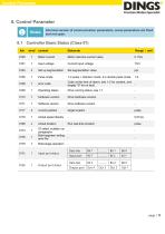
Control Parameter 8. Control Parameter Notes Informal version of communication parameters, some parameters are fixed and not open. 8.1 Controller Basic Status (Class 01) Adr Range / unit Motor current Motor real-time current value Input voltage Current input voltage Pulse mode 1 is pulse + direction mode, 2 is double pulse mode error code Code at the time of alarm, see 1-2 for content, and display "0" for no fault Operating status Drive running status, see 1-1 hardware version Drive hardware version Software version Drive software version current position target location Actual speed...
Open the catalog to page 11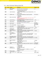
Control Parameter 8.2 Basic Parameter Setting (Class 02) Adr 0201 Range / unit Motor direction switching Select the motor running direction Set when the motor is stopped 1: user parameter reset 2: Clear the alarm (except for some hardware failure alarms) 3: drive restart Stop current ratio (effective in open loop mode) 0: open loop 1: closed loop Default: 1 *After changing the parameters, the power must have to turn off and on. The smaller the value, the smoother the motor runs, but the higher the delay Filter coefficient of input pulse. The larger the value, the lower the input frequency...
Open the catalog to page 12All Jiangsu DINGS' Intelligent Control Technology Co. catalogs and technical brochures
-
 General Catalog
295 Pages
-
 Simple Brochure
36 Pages
-
 DS-BVS-FETC-FCAO_Hardware Manual
18 Pages
-
 DS-BVS-BVM-Series_Reference Manual
181 Pages
-
 DINGS Servo Studio Manual
57 Pages
-
 DS-BVM-FETC-FCAO_Hardware Manual
15 Pages
-
 DS-OL42-ICAO_Technical Manual
53 Pages
-
 DS-CLS9-FETC-2I_Technical Manual
43 Pages
-
 DS-CLS9-FETC-2A_Technical Manual
43 Pages
-
 DS-CLS9-FETC_Technical Manual
17 Pages
-
 DS-CLS9-FCAO_Technical Manual
59 Pages
-
 DS-OLS10-FSC_Technical Manual
12 Pages
-
 DS-OLS8-FRS4_Technical Manual
30 Pages
-
 DS-OLS7-FRS4_Technical Manual
29 Pages
-
 DS-OLS8-FPD_Technical Manual
16 Pages
-
 DS-OLS4-FPD_Technical Manual
17 Pages
-
 DS-OLS22_FPD_Technical Manual
16 Pages
-
 DS-OLS2-FPD_Technical Manual
16 Pages
-
 DS-CLS9-FRS4_Technical Manual
21 Pages