Catalog excerpts

Closed Loop Stepping Motor Driver VER 1.4
Open the catalog to page 1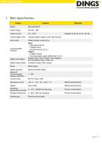
Main Specification 1. Main Specification Project Power supply Output current Control object motor 2-phase bipolar stepper motor with encoder Drive mode PWM constant current drive Communication Interface Digital input details Input ・ High-speed input 2 ・ 5 digital inputs ・ Encoder input (A, B, Z) Output ・ 3 digital outputs ・ Encoding signal output (differential A, B, Z) Enable, Alarm reset, Positive limit, Negative limit, Emergency stop, Origin, etc. Digital output details In position output, Alarm output Brake output Digital indication Status and fault display EtherCAT Communication address...
Open the catalog to page 3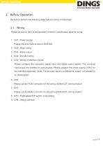
Before Operation 2. Before Operation Be sure to perform the following tasks before turning on the power. Please be sure to refer to the specified connector specification table for wiring. 1. CN1 : Power supply Please use wire material above AWG #20. 2. CN2 : Motor wiring 3. CN3 : Brake output 4. CN4 : Encoder wiring 5. CN5 : Wiring of interface signals Please configure the necessary digital input and digital output signals. The universal input/output are isolated by optocouplers. Please prepare the power supply (+24V) for the interface separately. (Note: The encoder signal is a differential...
Open the catalog to page 4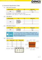
Connector Specification Table 3. Connector Specification Table 3.1 CN1 (Power Supply) Terminal number Signal name Pay attention to the power polarity when wiring Specification of wire: AWG 20 ~ AWG 16 (multi strand wire) CN2 (Motor) Terminal number Signal name Signal name CN3 (Brake Output) Terminal number 1. The maximum output current is 500mA, without external relay 2. To set it default, this function is disabled at DINGS’. When you need this function, please turn it on and set the relevant parameters through the debugging software. Signal name Signal name Schematic Diagram
Open the catalog to page 5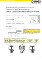
Connector Specification Table Pay attention to the polarity of the encoder power supply when wiring Use wire specification: AWG28~AWG18 (multi-stranded wire) The terminal is a pull back spring connection and adopts the front wiring mode. It is very easy to operate when a special screwdriver is used. Dimension drawing Fasten the terminal block with the special tool When tightening the terminal, Please use a blade width 0.4×2.5 screw driver. For example:Phoenix Contact Screw Driver (Product No:1205037,Model SZS 0.4×2.5) Wiring Method: ① Strip Length:7~8mm Do not apply a layer of solder to the...
Open the catalog to page 6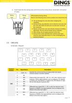
Connector Specification Table ③ Insert lead into the wiring area and remove the screw driver. Automatic connection of wires. Wiring ※Precautions during wiring Observe the following items and be careful not to break the wire. Do not damage the core wire when stripping the During wiring, pay attention not to kink the core wire and the core wire shall not leak out to avoid short circuit of the conductor. Please connect the core wire directly instead of welding. Otherwise, the line will be broken due to vibration After wiring, do not apply pressure to the wire. Screw driver of the...
Open the catalog to page 7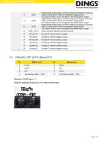
Connector Specification Table Single-ended output signal, common cathode connection, maximum output current 50mA, maximum withstand voltage 30Vdc. The output function can be configured, the default alarm output Single-ended output signal, common cathode connection, maximum output current 50mA, maximum withstand voltage 30Vdc. The output function can be configured, the default alarm output Single-ended output signal, common cathode connection, maximum output current 50mA, maximum withstand voltage 30Vdc. The output function can be configured, the default alarm output Output common cathode...
Open the catalog to page 8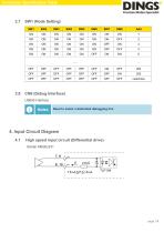
Connector Specification Table CN8 (Debug Interface) USB-B Interface Need to select a dedicated debugging line 4. Input Circuit Diagram 4.1 High speed input circuit (Differential drive) Similar AM26LS31
Open the catalog to page 9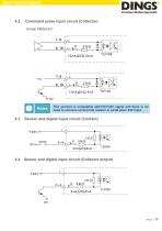
Input Circuit Diagram Command pulse input circuit (Collector) Similar AM26LS31 This product is compatible with+5V/+24V signal and there is no need to connect current limit resistor in serial when 24V input. Sensor and digital input circuit (Contact) 4.4 Sensor and digital input circuit (Collector output)
Open the catalog to page 10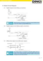
Output Circuit Diagram 5. Output Circuit Diagram 5.1 Digital output circuit (Relay connection) When the relay is connected, it is required to connect diodes at both ends of the relay(for example IN4000 series). Digital output circuit (Optocoupler connection) Differential output circuit (Encoder output) The encoder output is not isolated by optocoupler. Before power on, please confirm whether the wiring is correct and whether there is short circuit so as to avoid introducing 24V power supply on the port and damaging the upper master and driver.
Open the catalog to page 11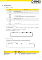
Status display Display Description Motor rotation display Lights when the motor rotates, lights off when stopped Device enable status The device enable indicator is on and the device disable indicator is off. Displayed in command input Command input light is on Displayed in CONNECT CONNECT light is on Node number display The Station Address is displayed verbatim and ends with H. After the CONNECT connection is successful, only the status is displayed. Example : Station Address : 45H Alarm display The alarm code is displayed verbatim and flashes, ending with E Example : Alarm Code E8H Alarm...
Open the catalog to page 12
Under Voltage Power input is less than 18V Over Voltage Power input is greater than 60V Over Temperature MOS tube driver voltage failure The temperature of the drive radiator reaches 85°C or more MOS tube driver voltage failure Spare Abnormal EEPROM data writing Abnormal EEPROM data writing Position Error Position Error Current Overload Current Overload Encoder Error Abnormal Communication Encoder Wiring Error The communication bus is abnormal. When the device is enabled, the communication line is disconnected or the communication quality is unstable Abnormal EEPROM data reading Emergency...
Open the catalog to page 13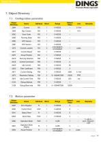
Object Directory Configuration parameter Object Directory Default Value Error Code Running State Current Location Current Speed Actual Position Running Direction Control Command Idle Current Filter Coefficient Current Setting Resolution Setting Idle Current Time Debug Address Debug Baud rate Motion parameter Object Directory Default Value Error Register Control Word Status Word Quick Stop Operation Mode Operation Mode Display Actual Position
Open the catalog to page 14All Jiangsu DINGS' Intelligent Control Technology Co. catalogs and technical brochures
-
 General Catalog
295 Pages
-
 Simple Brochure
36 Pages
-
 DS-BVS-FETC-FCAO_Hardware Manual
18 Pages
-
 DS-BVS-BVM-Series_Reference Manual
181 Pages
-
 DINGS Servo Studio Manual
57 Pages
-
 DS-BVM-FETC-FCAO_Hardware Manual
15 Pages
-
 DS-OL42-ICAO_Technical Manual
53 Pages
-
 DS-CLS9-FETC-2I_Technical Manual
43 Pages
-
 DS-CLS9-FETC-2A_Technical Manual
43 Pages
-
 DS-CLS9-FCAO_Technical Manual
59 Pages
-
 DS-OLS10-FSC_Technical Manual
12 Pages
-
 DS-OLS8-FRS4_Technical Manual
30 Pages
-
 DS-OLS7-FRS4_Technical Manual
29 Pages
-
 DS-OLS8-FPD_Technical Manual
16 Pages
-
 DS-OLS4-FPD_Technical Manual
17 Pages
-
 DS-OLS22_FPD_Technical Manual
16 Pages
-
 DS-OLS2-FPD_Technical Manual
16 Pages
-
 DS-CLS9-FRS4_Technical Manual
21 Pages
-
 DS-CLS9-FRS4-01_Technical Manual
29 Pages