Catalog excerpts
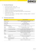
Functional features/ Technical parameters Enter the power supply : DC 24V ~ 48V Motor output current per axis (peak) : 0.4 ~ 6.5A Suitable for incremental open-loop and closed-loop motors EtherCAT communication control, support control mode PP, PV, TQ, HM, CSP, CSV Photocoupler input function Motor short circuit protection, undervoltage protection, overvoltage protection, overcurrent protection and other functions 2. Technical parameters Drive model Power supply Suitable for two-phase hybrid incremental stepper motor, maximum adaptation 6.5A (peak) DC 24V~48V Output current Drive mode...
Open the catalog to page 3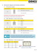
Schematic diagram and interface definition 3. Schematic diagram and interface definition 3.1 Terminal number Signal name Pay attention to the polarity of the power supply when wiring Wire specifications: AWG20~AWG16 (multi-stranded wire) CN2 / CN6 (Axis 1 / Axis 2 motor wiring) Terminal number Signal name CN3 / CN7 (Axis 1 / Axis 2 holding brake output) Terminal number Signal name BRK+ brake output is positive BRK - Negative brake output 1. The maximum output current is 500mA, no external relay is required 2. This function is turned off by factory by default, when this function is needed,...
Open the catalog to page 4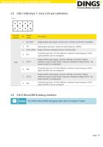
Schematic diagram and interface definition CN5 / CN9 (Axis 1 / Axis 2 I/O port definition) Terminal number Signal name Single-ended input signal common end, common via 24VDC compatible High-speed input port, maximum input frequency 100KHz Output Common Cathode Common Terminal (0V) Universal input port, 18~24V effective, maximum input frequency 1KHz, signal definition can be configured Single-ended output signal, common cathode connection method, maximum output current 50mA, maximum withstand voltage 30Vdc. The output function is configurable Universal input port, 18~24V effective, maximum...
Open the catalog to page 5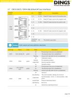
Schematic diagram and interface definition Terminal number Signal name EtherCAT data is sent on the positive side EtherCAT data is sent to the negative side EtherCAT data receives the positive side EtherCAT data receives the negative side Connector housing RJ45 network port lamp definition description Name Color green Physical layer links are not established The physical layer link is established flashing single flash Pre-operational status Security operation status Physical layer links are not established The physical layer link is established Initialization status Operation status...
Open the catalog to page 6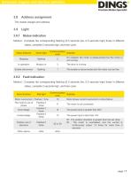
Schematic diagram and interface definition Address assignment The master assigns and address Status indication Method : Complete the corresponding flashing (0.5 seconds low, 0.5 seconds high) times in different states, complete 2 seconds high, and then cycle. Communication Illustrate code On enabled, the motor is phase-locked but the motor is 2 not running Status features Green light Enable disconnect The enable is disconnected and the motor can be free Fault indication Method : Complete the corresponding flashing (0.5 seconds low, 0.5 seconds high) times in different states, complete 2...
Open the catalog to page 7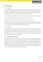
Power supply The chopper driver constantly changes the magnitude and direction of the voltage at the winding terminal of the motor while sensing the current to obtain an accurate phase current. If high efficiency and low noise are to be guaranteed at the same time, the driver supply voltage is at least 5 times the rated phase voltage of the motor (i.e. the rated phase current × phase resistance of the motor). If you need better high-speed performance from your motor, you need to increase the drive supply voltage. If a regulated power supply is used, the supply voltage must not exceed 48V....
Open the catalog to page 8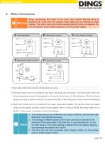
Motor connection 5. Motor Connection When connecting the motor to the drive, first confirm that the drive is powered off. Verify that the unused motor leads are not shorted to other Warning objects. The motor cannot be disconnected while the drive is energized. Do not connect the motor leads to ground or to the power supply. 1) Four-wire motors can only be connected in one way. 2) Six-wire motors can be connected in two ways: full group and half group. In the full group mode, the motor has greater torque at low speeds, but it cannot run as fast as in the half group. When the whole group is...
Open the catalog to page 9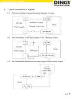
Typical connection of signals 6. Typical connection of signals 6.1 The input signal is connected using a switch or relay The connection of the input signal to the NPN-type output The connection method of the output signal sink current output
Open the catalog to page 10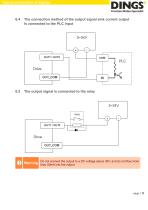
Typical connection of signals The connection method of the output signal sink current output Is connected to the PLC input The output signal is connected to the relay Do not connect the output to a DC voltage above 30V, and do not flow more Warning than 50mA into the output
Open the catalog to page 11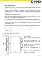
Wiring requirements / Installation size 7. Wiring requirements 1) In order to prevent the driver from being disturbed, it is recommended that the control signal use a shielded cable, and the shielding layer is shorted to the ground, except for special requirements, the shielded wire of the control signal cable is grounded on a single end: the host computer of the shielded wire is grounded, and the driver end of the shielded wire is suspended. Only the same point of grounding is allowed in the same machine, if it is not a real grounding wire, it may interfere seriously, and the shield is not...
Open the catalog to page 12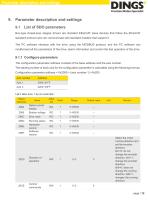
Parameter description and settings 9. Parameter description and settings 9.1 Bus-type closed-loop stepper drivers are standard EtherCAT slave devices that follow the EtherCAT standard protocol and can communicate with standard masters that support it. The PC software interacts with the drive using the MODBUS protocol, and the PC software can modify/read all the parameters of the drive, alarm information and control the test operation of the drive 9.1.1 Configure parameters The configuration parameter address consists of the base address and the axis number. The starting number of each axis...
Open the catalog to page 13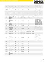
Parameter description and settings The stop current is a percentage of the operating current. 0: open loop, 1: Closed loop. The smaller the value, the smoother the motor runs, but the higher the latency. Idle current Motor mode settings Filter factor Current setting Resolution settings Idle current time Encoder resolution Location outof-tolerance threshold Positive limit Negative limit Memory control switch IN1 function selection IN2 function selection IN3 function selection OUT1 function selection OUT2 function selection Enter the port logic Output port logic Position out-oftolerance...
Open the catalog to page 14All Jiangsu DINGS' Intelligent Control Technology Co. catalogs and technical brochures
-
 General Catalog
295 Pages
-
 Simple Brochure
36 Pages
-
 DS-BVS-FETC-FCAO_Hardware Manual
18 Pages
-
 DS-BVS-BVM-Series_Reference Manual
181 Pages
-
 DINGS Servo Studio Manual
57 Pages
-
 DS-BVM-FETC-FCAO_Hardware Manual
15 Pages
-
 DS-OL42-ICAO_Technical Manual
53 Pages
-
 DS-CLS9-FETC-2A_Technical Manual
43 Pages
-
 DS-CLS9-FETC_Technical Manual
17 Pages
-
 DS-CLS9-FCAO_Technical Manual
59 Pages
-
 DS-OLS10-FSC_Technical Manual
12 Pages
-
 DS-OLS8-FRS4_Technical Manual
30 Pages
-
 DS-OLS7-FRS4_Technical Manual
29 Pages
-
 DS-OLS8-FPD_Technical Manual
16 Pages
-
 DS-OLS4-FPD_Technical Manual
17 Pages
-
 DS-OLS22_FPD_Technical Manual
16 Pages
-
 DS-OLS2-FPD_Technical Manual
16 Pages
-
 DS-CLS9-FRS4_Technical Manual
21 Pages
-
 DS-CLS9-FRS4-01_Technical Manual
29 Pages