Catalog excerpts
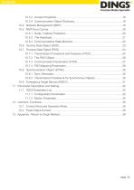
10.3.3 Access Properties………………………………………………………………..18 10.3.4 Communication Object Dictionary……………………………………………...18 10.4 Network Management (NMT) …………………………………………………………..19 10.5 NMT Error Control…………..……………………………………………………………20 10.5.1 Node / Lifetime Protection………………………..……………………………..20 10.5.2 The Heartbeat…………………………………………………………………….21 10.5.3 Communications State Machine………………………………………………..22 10.6 Service Data Object (SDO)………………………………………………..……………23 10.7 Process Data Object (PDO) …………………………………………………………….24 10.7.1 Transmission Framework and Features of PDO……………………………...24 10.7.2 The PDO...
Open the catalog to page 3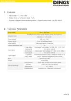
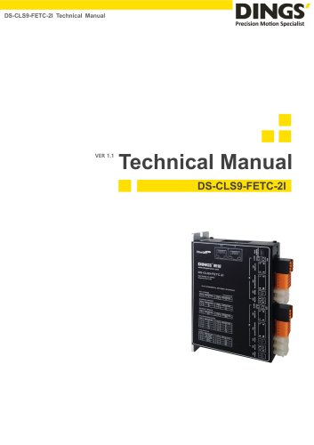
Main Specification 1. Features - Input power:DC 24V ~ 48V - Output rated current (peak value) : 6.5A - Support CANopen communication protocol,Support control mode PP, PV, HM,PT 2. Technical Parameters Drive model Adapted motor DS-CLS9-FCAO Suitable for two-phase hybrid stepping motor, the maximum adaptation is 6.5A (peak) Power supply Output current Drive method Full-bridge bipolar PWM drive Device initialization time Input signal Output signal 2 high-speed input signal 5 universal input signals 3 common output signal Size Weight Use surroundings 2s Optocoupler input voltage : H = 3.5 - 26V...
Open the catalog to page 4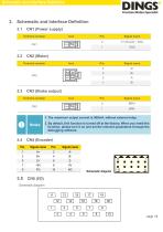
Schematic and Interface Definition 3. Schematic and Interface Definition 3.1 CN1 (Power supply) Terminal number Signal name Signal name CN2 (Motor) Terminal number CN3 (Brake output) Terminal number Signal name 1. The maximum output current is 500mA, without external relay. 2. By default, this function is turned off at the factory. When you need this function, please turn it on and set the relevant parameters through the debugging software. Signal name Signal name Schematic diagram
Open the catalog to page 5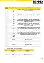
Schematic and Interface Definition Terminal number Signal name Describe the common terminal of single-ended input signal, common anode or common cathode Single-ended input signal IN1~IN5, 18~24V valid, maximum input frequency 10KHz, signal definition can be configured, IN1 defaults to positive limit, IN2 defaults to negative limit, IN3 defaults to origin, IN4 and IN5 defaults to general input Differential input signal IN6, 5~24V is valid, the maximum input frequency is 500KHz, the signal definition can be configured, the default is the probe input signal 1 Differential input signal IN7,...
Open the catalog to page 6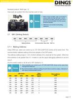
Schematic and Interface Definition Standard product: RJ45 type × 2 View each pin position from the insertion point of view 1. When using multiple units connected in series, when the last CN7 pin 1 and 8 are short-circuited, and the 2-pin and 7pin are short-circuited, it is the access terminal resistor. 2. CN6 does not contain terminating 3.7.1 Mailing Address Using CAN bus, users can control up to 127 DS-CLS9-FCAO drives at the same time. The communication address setting of the drive adopts a 5-bit DIP switch. The address setting range is 1-32, of which address 32 is reserved for the...
Open the catalog to page 7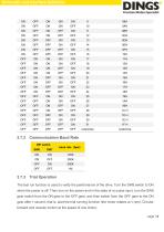
Schematic and Interface Definition 3.7.2 Communication Baud Rate DIP switch baud rate(bps) 3.7.3 Trial Operation The test run function is used to verify the performance of the drive. Turn the SW8 switch to ON when the power is off. Then turn on the power and in the state of no pulse input, turn the SW8 gear switch from the ON gear to the OFF gear, and then switch from the OFF gear to the ON gear after 1 second, that is, start the trial running function (the motor rotates at 1 rpm). Circular forward and reverse motion at the speed of one circle). page
Open the catalog to page 8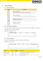
Status Display display Motor rotation display Lights when the motor rotates, lights off when stopped Device enable status The device enable indicator is on and the device disable indicator is off. Displayed in command input Command input light is on Displayed in CONNECT CONNECT light is on Site Number Display The site number is displayed verbatim and ends with H. After the CONNECT connection is successful, only the status is displayed. Example : Site number : 45H Alarm Display The alarm code is displayed verbatim and flashes, ending with E Example : Alarm code E8 Alarm code Alarm /warning...
Open the catalog to page 9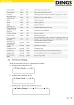
Power input is less than 18V Power input is greater than 60V The temperature of the drive radiator reaches 85°C or more MOS tube driver voltage failure MOS tube driver voltage failure Factory reserved Factory reserved Factory reserved EEPROM data writing abnormal Current overload Current overload Encoder error Encoder wiring error Communication abnormal The communication bus is abnormal. When the device is enabled, the communication line is disconnected or the communication quality is unstable EEPROM data read abnormal Emergency stop Emergency stop Positive limit On the positive limit or...
Open the catalog to page 10All Jiangsu DINGS' Intelligent Control Technology Co. catalogs and technical brochures
-
General Catalog
295 Pages
-
Simple Brochure
36 Pages
-
DS-BVS-FETC-FCAO_Hardware Manual
18 Pages
-
DS-BVS-BVM-Series_Reference Manual
181 Pages
-
DINGS Servo Studio Manual
57 Pages
-
DS-BVM-FETC-FCAO_Hardware Manual
15 Pages
-
DS-OL42-ICAO_Technical Manual
53 Pages
-
DS-CLS9-FETC-2I_Technical Manual
43 Pages
-
DS-CLS9-FETC-2A_Technical Manual
43 Pages
-
DS-CLS9-FETC_Technical Manual
17 Pages
-
DS-OLS10-FSC_Technical Manual
12 Pages
-
DS-OLS8-FRS4_Technical Manual
30 Pages
-
DS-OLS7-FRS4_Technical Manual
29 Pages
-
DS-OLS8-FPD_Technical Manual
16 Pages
-
DS-OLS4-FPD_Technical Manual
17 Pages
-
DS-OLS22_FPD_Technical Manual
16 Pages
-
DS-OLS2-FPD_Technical Manual
16 Pages
-
DS-CLS9-FRS4_Technical Manual
21 Pages
-
DS-CLS9-FRS4-01_Technical Manual
29 Pages


