Catalog excerpts
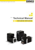
DS-CL28_42-SA User Program (GUI) Function
Open the catalog to page 1
Connecting PC with Drive Module.………...…………..…...……………………….7
Open the catalog to page 2
Safety Pre-caution General Precaution Contents of this manual are subject to change without prior notice for functional improvement, change of specifications or user’s better understanding. When the manual is damaged or lost, please contact with DINGS’ distributors or our company at the address on the last page of the manual. Our company is not responsible for a product breakdown due to user’s dismantling for the product, and such a breakdown is not guaranteed by the warranty. Before installation, operation and repairing the DS-CL28/42-SA thoroughly read the manual and fully understand the...
Open the catalog to page 3
Safety Pre-caution Carefully move the DS-CL28/42-SA. Otherwise, the product may get damaged or user’s foot may get injured by dropping the product. Use non-flammable materials such as metal in the place where the DSCL28/42-SA is to be installed. Otherwise, a fire may occur. When installing several DS-CL28/42-SA in a sealed place, install a cooling fan to keep the ambient temperature of the DS-CL28/42-SA as 50℃ or lower. Otherwise, a fire or other kinds of accidents may occur due to overheating. The process of installation, connection, operation, checking and repairing should be done with...
Open the catalog to page 4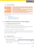
Safety Pre-caution / Installation and Connection of the Program Stop to supply power to the main circuit and wait for a while before checking or repairing the DS-CL28/42-SA. Electricity remaining in the capacitor may occur danger. Do not change cabling wile power is being supplied. Otherwise, the user may get injured or the product may get damaged. Do not reconstruct the DS-CL28/42-SA. Otherwise, an electric shock may occur or the reconstructed product cannot get after service. This manual describes how to operate User Program(GUI) for DS-CL28/42-SA. For more information, refer related...
Open the catalog to page 5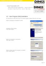
Installation and Connection of the Program 2) User Program(GUI) in PC : After connect the User Program(GUI), be check in ‘About Plus-R GUI…’menu in ‘Help’ menu. User Program (GUI) Installation By executing ‘Ezi-MOTION Plus-R V6 Install’ program, please follow the next steps. Select a language of installation screen. Installation Start window. Click ‘Next’ button Select all installation components. Click ‘Next’ button. Select a folder where the program is installed Click ‘Ins
Open the catalog to page 6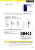
Installation and Connection of the Program Then installation is completed at the selected folder, ‘Program Files/DINGS/Ezi MOTION Plus-R V6’ folder is created and also GUI icon and program folders are installed. 1) Include folder : *dll, *.lib, *.h files 2) Example folder : source code for sample 3) PT Samples folder : sample data tiles for position table. Connecting PC with Drive Module Execute which is User Program(GUI), click ‘Connect’ button, and the following window will be displayed. To assign the port number of RS-232 or USB which is connected with drive module at the PC. Baud rate...
Open the catalog to page 7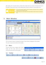
Installation and Connection of the Program / Main Window After setting, click ‘Connect’ button, and the drive module will try to connect 16 drives from 0 to 15 (firmware of same level version) at the setting speed through a pertinent communication port. The communication speed of drive modules connected with one network must be set to the same value. When they are not connected, the user needs to check the port or the baud rate. This is the basic window to operate the program. Each window is displayed in this window. The user can open each window with a toolbar. There are ‘View’ menu to...
Open the catalog to page 8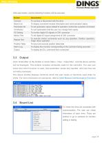
Main Window Click each button, and the following functions will be executed Button To connect or disconnect with the drive Board List To display connected module information and communication status Parameter list To set parameter values related to operation control like a position command To sort parameters that the user can change them easily To monitor digital I/O signals of CN1 connector Motion Test To set digital I/O signal assignment of CN1 connector Repeat Test To execute motion commands such as Jog operation, Position operation, Origin return operation Position Table To input and...
Open the catalog to page 9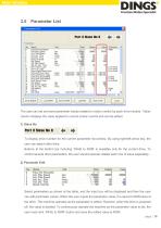
Main Window Parameter List The user can set and save parameter values related to motion control by each drive module. ‘Value’ column displays the value applied to current motion control and can be edited. 1) Slave No To display drive number for the current parameter list window. By using right/left arrow key, the user can select other drive. Buttons at the bottom bar including ‘SAVE to ROM’ is available only for the current drive. To control several drive parameters, the user should execute related each one of slave separately. 2) Parameter Edit Select parameters as shown at the table, and...
Open the catalog to page 10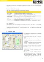
Main Window When the input value is out of right range, it is displayed in red color. The value cannot be inputted in RAM of the drive. 3) Parameter List Window Buttons Click each button, and the following functions will be executed. Button Converts all parameter values into ‘Default Value’. Converts ‘Value’ items into values saved to the ROM area. Saves ‘Value’ items to the ROM area. (Even though the drive is powered off, they are not deleted.) Load File Sets ‘Value’ items to the values saved to an external file. Saves the current values to an external file. (The user defines folder...
Open the catalog to page 11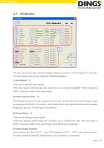
Main Window The user can set and check control I/O signals related to operation control through CN1 connecter. The next window is the sample setting of I/O Monitoring status. 1) Input Signal : ① There are 32 definable input signals. When each signal is [ON] through CN1 connecter, icon is changed into ‘green’. When the signal is [OFF], it returns to ‘white’ to the original state. 2) Virtual Input Function : ② Even though the input pin is not assigned at all, the user can click each button and virtually change the signal into [ON]/[OFF]. For instance, click ‘Pause’ button, and the stop...
Open the catalog to page 12All Jiangsu DINGS' Intelligent Control Technology Co. catalogs and technical brochures
-
General Catalog
295 Pages
-
Simple Brochure
36 Pages
-
DS-BVS-FETC-FCAO_Hardware Manual
18 Pages
-
DS-BVS-BVM-Series_Reference Manual
181 Pages
-
DINGS Servo Studio Manual
57 Pages
-
DS-BVM-FETC-FCAO_Hardware Manual
15 Pages
-
DS-OL42-ICAO_Technical Manual
53 Pages
-
DS-CLS9-FETC-2I_Technical Manual
43 Pages
-
DS-CLS9-FETC-2A_Technical Manual
43 Pages
-
DS-CLS9-FETC_Technical Manual
17 Pages
-
DS-CLS9-FCAO_Technical Manual
59 Pages
-
DS-OLS10-FSC_Technical Manual
12 Pages
-
DS-OLS8-FRS4_Technical Manual
30 Pages
-
DS-OLS7-FRS4_Technical Manual
29 Pages
-
DS-OLS8-FPD_Technical Manual
16 Pages
-
DS-OLS4-FPD_Technical Manual
17 Pages
-
DS-OLS22_FPD_Technical Manual
16 Pages
-
DS-OLS2-FPD_Technical Manual
16 Pages
-
DS-CLS9-FRS4_Technical Manual
21 Pages
-
DS-CLS9-FRS4-01_Technical Manual
29 Pages


