Catalog excerpts

DS-CL28_42-SA Communication Function Technical Manual
Open the catalog to page 1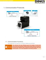
Communication Protocols 1.1 Communication Functions DS-CL28/42-SA can control up to 16 axis by multidrop link at RS-485 Pay attention that when Windows goes into standby or power-save mode, serial communication might be disconnected. When the system is recovered from standby mode, it should be connected again with serial communication. This is also applicable to the library provided.
Open the catalog to page 5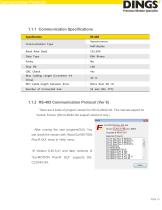
Communication Protocols 1.1.2 RS-485 Communication Protocol (Ver 6) There are 2 kinds of program version for DS-CL28/42-SA. This manual support for Version 6 level. (DS-CL28/42-SA support version 6 only.) After running the user program(GUI), You can check the version with ‘About Ezi-MOTION Plus-R GUI’ menu in ‘Help’ menu. ※ Version 6.45.5.41 and later versions of “Ezi-MOTION Plus-R GUI” supports DSCL28/42-SA
Open the catalog to page 6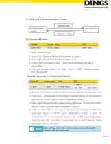
Communication Protocols (1) Overview of Communication Frame ① 0xAA : Delimited byte ② 0xAA 0xCC : Displays that the Frame locates in header. ③ 0xAA 0xEE : Displays that the Frame locates in tail. ④ If any of the Frame data is ‘0xAA’, ‘0xAA’ should be added right after it. (byte stuffing 1) ) ⑤ If any data following ‘0xAA’ is not ‘0xAA’, ‘0xCC’ or ‘0xEE’, it displays that an error has occurred. Detailed Frame Data is configured as follows: ① Slave ID : Dive module number (0~15) connected to the PC communication port. ② Frame type : To designate command type of relevant frames. For the...
Open the catalog to page 7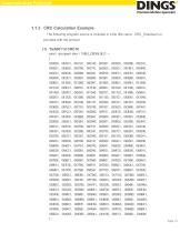
Communication Protocols 1.1.3 CRC Calculation Example The following program source is included in a file (file name : CRC_Checksum.c) provided with the product.
Open the catalog to page 8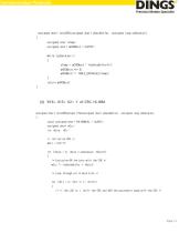
Communication Protocols
Open the catalog to page 9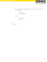
Communication Protocols
Open the catalog to page 10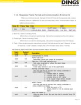
Communication Protocols 1.1.4 Response Frame Format and Communication Error(ver 6) When any command is sent, the basic format of Frame at the response side is same. However, there is a difference in case of Frame Data, which ‘communication status’ is added as shown below. ① Slave ID : Same to sending Frame. (When this is not same to sending data, it should be recognized as the error status.) ② Frame type : Same to sending Frame. (When this is not same to sending data, it should be recognized as the error status.) ③ Data : When simple executive instructions are sent, this data cannot be...
Open the catalog to page 11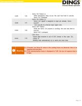
Communication Protocols (1) If ‘Header’ and ‘Slave ID’ values in the sending Frame are abnormal, there is no response from the drive. (2) If the communication status is displayed to ‘130’, the size of response data is ‘0’ byt
Open the catalog to page 12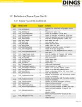
Communication Protocols 1.2 Definition of Frame Type (Ver 6) 1.2.1 Frame Type of DS-CL28/42-SA
Open the catalog to page 13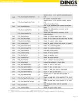
Communication Protocols Control Parameter *1) V06.01.30.22 and later versions(DS-CL28/42-SA) of firmware supports this functions.
Open the catalog to page 14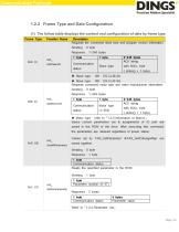
Communication Protocols 1.2.2 Frame Type and Data Contiguration (1) The follow table displays the content and configuration of data by frame type
Open the catalog to page 15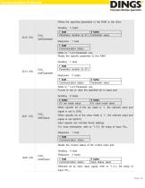
Communication Protocols Control Parameter
Open the catalog to page 16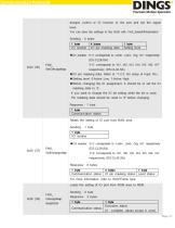
Communication Protocols
Open the catalog to page 17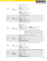
Communication Protocols Control Parameter
Open the catalog to page 18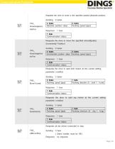
Communication Protocols Control Parameter
Open the catalog to page 19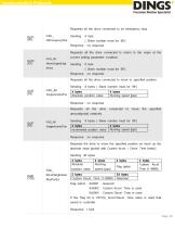
Communication Protocols Control Parameter
Open the catalog to page 20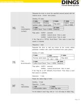
Communication Protocols
Open the catalog to page 21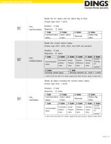
Communication Protocols
Open the catalog to page 22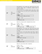
Communication Protocols
Open the catalog to page 23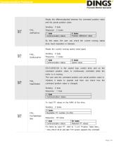
Communication Protocols
Open the catalog to page 24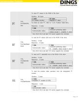
Communication Protocols
Open the catalog to page 25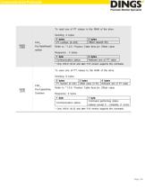
Communication Protocols
Open the catalog to page 26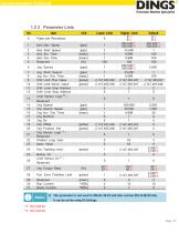
Communication Protocols 1) This parameter is not used in V06.01.30.22 and later version (DS-CL28/42-SA). It can be set by using IO Settings.
Open the catalog to page 27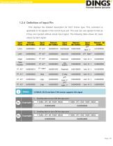
Communication Protocols 1.2.4 Definition of Input Pin This displays the detailed description for 0x21 Frame type. This command is applicable to 32 signals in the control input port. The user can use signals for test as if they are inputted without actual input signal. The following table shows bit mask values by each signal. 1) V06.01.30.22 and later F/W version supports this signal. 1. Sending data to turn ON the Jog+ port Example 2. Sending data to turn ON the Jog+ port
Open the catalog to page 28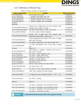
Communication Protocols 1.2.5 Definition of Status Flag Refer to ‘motion_define.h’ of include files 1) Only V06.01.30.22 and later F/W version supports this flag. Page | 2
Open the catalog to page 29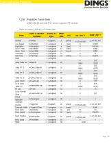
Communication Protocols 1.2.6 Position Tanle Item (V06.01.30.22 and later F/W version supports PT function) Refer to ‘motion_define.h’ of include files
Open the catalog to page 30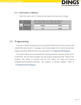
Communication Protocols 1.2.7 Information of Motors Firstly the number and 2~3 characters are display the motor size and length 28L : Motor Flange size is 28mm and Long size Second field is the motor maker information. Programming There are 2 method of programming for driving DS-CL28/42-SA The first is normally used method that using Visual C++ language under window system of PC. Library that serviced together with DS-CL28/42-SA have to be used. Refer to 「2. Library for PC Program」 The second method can be accomplished by sending command characters directly to DSCL28/42-SA. The user have to...
Open the catalog to page 31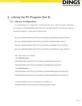
2. Library for PC Program (Ver 6) 2.1 Library Configuration To use this library, C++ header file(*.h) and library file(*.lib or *.dll) are required. These files are included in “\\DINGS\\Ezi-MOTION Plus-RnE\\include\\” The following contents should be included in a source file for development. #include “\\DINGS\\Ezi-MOTION Plus-RnE\\include\\FAS_EziMotionPlusR.h” #include “\\DINGS\\Ezi-MOTION Plus-RnE\\include\\COMM_Define.h” #include “\\DINGS\\Ezi-MOTION Plus-RnE\\include\\MOTION_DEFINE.h” #include “\\DINGS\\Ezi-MOTION Plus-RnE\\include\\ReturnCodes_Define.h” Also, library files are as...
Open the catalog to page 32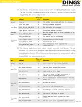
(1) The following table describes values returned when each library(DLL) function is used. The user can check the values returned at the library(DLL) function. In case of low-level programming, this service not provided. (2) The following table shows return values included commonly in all libraries. The user can check - 31 - Library for PC Program (Ver6) the result (communication status, running status) judged by the drive. When the user develops programs by using protocols without libraries (DLL), they are available as well.
Open the catalog to page 33All Jiangsu DINGS' Intelligent Control Technology Co. catalogs and technical brochures
-
General Catalog
295 Pages
-
Simple Brochure
36 Pages
-
DS-BVS-FETC-FCAO_Hardware Manual
18 Pages
-
DS-BVS-BVM-Series_Reference Manual
181 Pages
-
DINGS Servo Studio Manual
57 Pages
-
DS-BVM-FETC-FCAO_Hardware Manual
15 Pages
-
DS-OL42-ICAO_Technical Manual
53 Pages
-
DS-CLS9-FETC-2I_Technical Manual
43 Pages
-
DS-CLS9-FETC-2A_Technical Manual
43 Pages
-
DS-CLS9-FETC_Technical Manual
17 Pages
-
DS-CLS9-FCAO_Technical Manual
59 Pages
-
DS-OLS10-FSC_Technical Manual
12 Pages
-
DS-OLS8-FRS4_Technical Manual
30 Pages
-
DS-OLS7-FRS4_Technical Manual
29 Pages
-
DS-OLS8-FPD_Technical Manual
16 Pages
-
DS-OLS4-FPD_Technical Manual
17 Pages
-
DS-OLS22_FPD_Technical Manual
16 Pages
-
DS-OLS2-FPD_Technical Manual
16 Pages
-
DS-CLS9-FRS4_Technical Manual
21 Pages
-
DS-CLS9-FRS4-01_Technical Manual
29 Pages


