Catalog excerpts

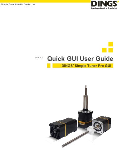
DINGS’ Simple Tuner Pro_Force Control Version Technical Guide Line Force Control Version Technical Guide Line DINGS’ Simple Tuner Pro
Open the catalog to page 1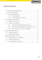
Product Information and Equipment Testing..…………..……8 Basic Setting and Operating Parameters and Control.……8 Input Port and Output Port Configuration………..………12 Parameter Setting Interface……………………………………….………
Open the catalog to page 2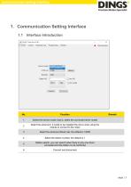
Communication Setting Interface 1. Communication Setting Interface 1.1 Interface Introduction Select the device model, that is, select the connected driver model Select the serial port, it needs to be installed the driver when using the module to connect to the motor Select the serial port Buad rate, the default is 19200 Select the station number, the default is 1 Station search, you can search when there is only one driver connected and the station is not confirmed
Open the catalog to page 3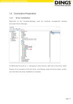
Communication Setting Interface Connection Preparation Driver Installation Right-click on My Computer-Manage, open the computer management interface, and select Device Manager. A USB Serial Port such as ① will appear in other devices, right click on the driver, select Browse of my computer to find the driver, click Browse, select the driver folder, confirm and click Next, the driver installation is complete.
Open the catalog to page 4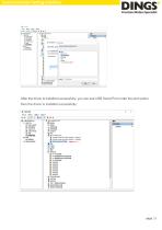
Communication Setting Interface After the driver is installed successfully, you can see USB Serial Port under the port option, then the driver is installed successfully.
Open the catalog to page 5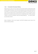
Communication Setting Interface Connection Parameter Setting Select the device model, the device model should be match with the connected driver model, and then select the serial port, which is the extra serial port of the computer after the device is connected. If you open the serial port module that the software is connected to first, you need to press the refresh button and restart Read the serial port, and then select the correct serial port. Then select the serial port baud rate, the default baud rate is 19200, just select it directly. The last one is the station number and usually...
Open the catalog to page 6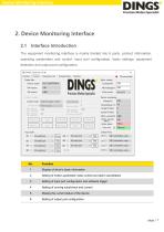
Device Monitoring Interface 2. Device Monitoring Interface 2.1 Interface Introduction The equipment monitoring interface is mainly divided into 6 parts, product information, operating parameters and control, input port configuration, basic settings, equipment detection and output port configuration. Display of driver's basic information Setting of motion parameter, basic control and alarm cancellation Setting of input port configuration and software trigger Setting of running subdivision and current Display the current status of the device Setting of output port configuration
Open the catalog to page 7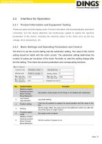
Device Monitoring Interface 2.2.1 Product Information and Equipment Testing These two parts are both display parts. Product information will be automatically read when connected, and the device detection will continuously update to realize the real-time parameters of the device, including the real-time status of the motor such as the bus voltage, drive temperature, etc. 2.2.2 Basic Settings and Operating Parameters and Control The first is to set the current setting and the subdivision setting. The value of the current setting should be match with the motor current. The subdivision setting...
Open the catalog to page 8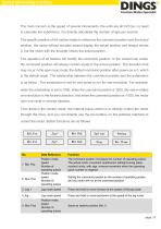
Device Monitoring Interface The main concern is the speed of several movements, the units are all 0.01rps, no need to calculate the subdivision, it is directly calculated the number of laps per second. The specific position of the motion needs to reference the command position and the actual position, the motor without encoder cannot display the actual position and always shows 0, but the motor with the encoder shows the actual position. The operation of all buttons will modify the command position. In the closed loop mode, the command position will always remain equal to the actual...
Open the catalog to page 9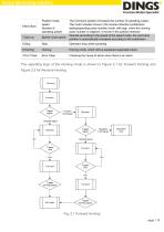
Device Monitoring Interface Position mode speed Number of operating pulses The command position increases the number of operating pulses. The motor actually moves in the reverse direction (subdivision setting/operating pulse number) circle, with sign, when the running pulse number is negative, it moves in the positive direction Operate according to the speed of the speed mode, the command position is automatically increased according to the subdivision Speed mode speed Operation stop while operating Homing mode, which will be explained separately below Error Clear Checking the cause of...
Open the catalog to page 10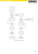
Device Monitoring Interface
Open the catalog to page 11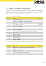
Device Monitoring Interface 2.2.3 Input Port and Output Port Configuration Through the input port configuration, simple control can be realized through external triggering. The functions with the same name as the above button in the drop-down list will not be repeated, mainly the functions not mentioned above. The first is the input port configuration. Function No. Port invalidation, no action Make port stop quickly, faster than deceleration stop Trigger positive limit signal Trigger negative limit signal Start multi- axes operation Pause multi- axes operation Stop multi- axes operation The...
Open the catalog to page 12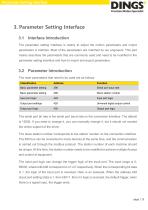
Parameter Setting Interface 3. Parameter Setting Interface 3.1 Interface Introduction The parameter setting interface is mainly to adjust the motion parameters and import parameters in batches. Most of the parameters are matched by our engineers. This part mainly describes the parameters that are commonly used and need to be modified in the parameter setting interface and how to import and export parameters. Parameter Introduction The main parameters that need to be used are as follows Classification Basic parameter setting Serial port baud rate Basic parameter setting Slave station number...
Open the catalog to page 13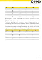
Parameter Setting Interface The modification of the output port logic is the same as the input port logic, so it will not be explained in details here. The universal digital output control corresponds to the universal digital output. When the universal output is set in the output port configuration, the output can be directly controlled by the data of this address. The input range is 0-15, and the data bit0-bit3 correspond to out1-out4 respectively. Here is an example where when the data at address 428 (universal digital output control) is 1, bit0=1 and out1 outputs high. Voltage flat in...
Open the catalog to page 14All Jiangsu DINGS' Intelligent Control Technology Co. catalogs and technical brochures
-
General Catalog
295 Pages
-
Simple Brochure
36 Pages
-
DS-BVS-FETC-FCAO_Hardware Manual
18 Pages
-
DS-BVS-BVM-Series_Reference Manual
181 Pages
-
DINGS Servo Studio Manual
57 Pages
-
DS-BVM-FETC-FCAO_Hardware Manual
15 Pages
-
DS-OL42-ICAO_Technical Manual
53 Pages
-
DS-CLS9-FETC-2I_Technical Manual
43 Pages
-
DS-CLS9-FETC-2A_Technical Manual
43 Pages
-
DS-CLS9-FETC_Technical Manual
17 Pages
-
DS-CLS9-FCAO_Technical Manual
59 Pages
-
DS-OLS10-FSC_Technical Manual
12 Pages
-
DS-OLS8-FRS4_Technical Manual
30 Pages
-
DS-OLS7-FRS4_Technical Manual
29 Pages
-
DS-OLS8-FPD_Technical Manual
16 Pages
-
DS-OLS4-FPD_Technical Manual
17 Pages
-
DS-OLS22_FPD_Technical Manual
16 Pages
-
DS-OLS2-FPD_Technical Manual
16 Pages
-
DS-CLS9-FRS4_Technical Manual
21 Pages
-
DS-CLS9-FRS4-01_Technical Manual
29 Pages


