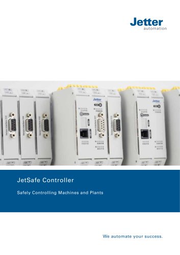
Catalog excerpts

We automate your success.
Open the catalog to page 1
This document has been compiled by Jetter AG with due diligence, and based on the known state of the art. Revisions and further development of our products are not automatically mentioned in a reviewed document. Jetter AG shall not be liable for errors in form or content, or for missing updates, as well as for damages or disadvantages resulting from such failure. Jetter AG Graeterstrasse 2 71642 Ludwigsburg Germany Phone Switchboard Sales Technical Hotline E-mail Technical Hotline Sales hotline@jetter.de sales@jetter.de Translation of the german original User Manual Revision
Open the catalog to page 2
1 Introduction 1.1 Information on this document This document forms an integral part of the product and must be read and understood prior to using it. It contains important and safety-related information for the proper use of the product as intended. Target groups This document is intended for specialists with appropriate qualifications. Only competent and trained personnel is allowed to put this device into operation. During the whole product life cycle, safe handling and operation of the device must be ensured. In the case of missing or inadequate technical knowledge or knowledge of this...
Open the catalog to page 6
2 Safety 2.1 General information At the time of placing on the market, this product corresponds to the current state of the art and meets the recognized safety rules. Besides this user manual, laws and regulations in the operator's country are relevant to the operation of the product. The operator is responsible for complying with the directives mentioned below: ■ Applicable legislation, rules, and regulations ■ Relevant accident prevention regulations ■ Accepted safety rules ■ EU directives and other country-specific regulations 2.2 Purpose 2.2.1 Intended use The Ethernet bus node...
Open the catalog to page 7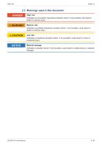
2.3 Warnings used in this document DANGER High risk Indicates an imminently hazardous situation which, if not avoided, will result in death or serious injury. Medium risk Indicates a potential hazardous situation which, if not avoided, could result in death or serious injury. Low risk Indicates a hazardous situation which, if not avoided, could result in minor or moderate injury. Material damage Indicates a situation which, if not avoided, could result in malfunctions or material damage.
Open the catalog to page 8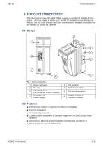
3 Product description The Ethernet bus node JX3-BN-ETH lets you set up remote I/O stations. It comprises a JX3 bus master to which up to 16 JX3 I/O modules can be directly connected. The bus node enables fast cyclic communication between controllers and the remote I/O station via Ethernet. Status indication Housing Connector X119: Connector for JX3 I/O modules Terminal X10: Power supply DIN rail latch Backplane module DIN rail release latch Sockets X14, X15: Ethernet interface 3.2 Features ■ Ethernet bus node for a maximum of 16 JX3 I/O modules ■ Fast I/O processing ■ Integrated 2-port...
Open the catalog to page 9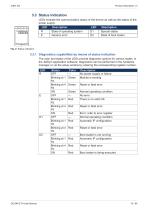
3.3 Status indication LEDs indicate the communication status of the device as well as the status of the power supply. LED R E Description State of operating system Generic error Description Special states State of boot loader 3.3.1 Diagnostics capabilities by means of status indication The color and status of the LEDs provide diagnostic options for various states. In the JetSym application software, diagnostics can be performed in the hardware manager or via the setup window by entering the corresponding register number. LED R Status OFF Blinking at 1 Hz Blinking at 4 Hz ON OFF Blinking at...
Open the catalog to page 10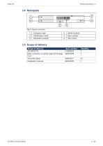
Company logo Certification mark Hardware revision Serial number Item number Item name 3.5 Scope of delivery Scope of delivery JX3-BN-ETH Male connector in spring-cage technology, 2-pin Terminal labels Installation manual
Open the catalog to page 11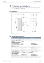
4 Technical specifications This chapter contains information on electrical and mechanical data, as well as on operating data of the JX3-BN-ETH. 4.2 Mechanical specifications Category Description Standards Weight 250 g Enclosure specifications Material Plastic Maximum height of fall Units within packing 1m DIN EN 61131-2 DIN EN 60068-2-31 Units within product pack- 0.3 m aging Vibration resistance Frequency sweeps 1 octave/minute, DIN EN 61131-2 sinusoidal DIN EN 60068-2-6 Constant amplitude 3.5 mm 5 Hz ≤ f ≤ 9 Hz Constant acceleration 1g 9 Hz ≤ f ≤ 150 Hz Number and direction 10 sweeps for...
Open the catalog to page 12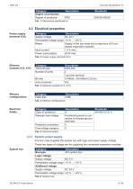
Category Degree of protection Degree of protection 4.3 Electrical properties Power supply (terminal X10) Category Supply voltage Permissible voltage range Reach Input current Power consumption Description DC 24 V -15 % ... +20 % Supply of the bus node and a maximum of 8 connected expansion modules 1.0 A max. 24 W max. Tab. 2: Power supply (terminal X10) Category Terminal type Number of ports Bit rate Auto-crossover Description RJ45 jack 2 1 port per terminal 10 Mbit/s, 100 Mbit/s (Cat 5e) Yes Memory configurations Category Flash disk Electrical Safety Category Class of protection Dielectric...
Open the catalog to page 13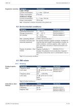
Expansion modules Category Logic voltage Current consumption Power consumption Additional voltage Current consumption Power consumption Tab. 7: Expansion modules connected to the system bus 4.4 Environmental conditions Category Operating temperature Storage temperature Air humidity Description Standards 0 … +50 °C DIN EN 61131-2 -40 … +70 °C DIN EN 60068-2-1 10 … 95 % DIN EN 60068-2-2 non-condensing Max. operating altitude: 2,000 m above sea level Corrosion immunity and No special protection against corrosion. Ambient air chemical resistance must be free from higher concentrations of acids,...
Open the catalog to page 14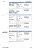
Parameter Values RF field, amplitude-modulated Frequency band 80 MHz … 2 GHz Test field strength 10 V/m AM 80 % with 1 kHz Criterion A ESD Discharge through air 8 kV Test peak voltage 6 kV Contact discharge 4 kV Test peak voltage 6 kV Criterion A 4.5.2 Shielded data and I/O lines Immunity to interference Parameter Values RF field, asymmetric, amplitude modulated Frequency band 0.15 … 80 MHz Test voltage 3V AM 80 % with 1 kHz Source impedance 150 Ω Criterion A Bursts Test voltage 1 kV tr/tn 5/50 ns Repetition frequency 5 kHz Criterion A Surge voltages, asymmetric, line to earth Common-mode...
Open the catalog to page 15All Jetter AG catalogs and technical brochures
-
JM-108 - Digital Servo Amplifier
106 Pages
-
JX3-DO16 Digital Output Module
136 Pages
-
JC-310-JM - Controller module
270 Pages


