JM-108 - Digital Servo Amplifier

JM-108 - Digital Servo Amplifier
The user manual for the JetMove 108 digital servo amplifier, item #60875640, revision 2.16.1, provides essential information on operation, installation, and maintenance. Jetter AG reserves the right to make product changes without documentation.
Contact Information
Jetter AG, based in Ludwigsburg, Germany, offers contact via phone, fax, or email for sales and technical support.
Manual Significance
The manual is crucial for the JetMove 108, covering transport, installation, operation, maintenance, and repair. Feedback for improvement is encouraged.
System Requirements
The manual pertains to the JetMove 108 with OS version 2.16.0.00.
Symbols Description
Symbols indicate warnings, cautions, important notes, and references for safe use.
Safety Instructions
The JetMove 108 complies with safety standards. Users must follow accident prevention regulations and safety rules. The device is not suitable for fail-safe systems.
Personnel Qualification
Different qualifications are needed for various product life cycle stages.
Modifications and Repairs
Unauthorized modifications void liability claims. Repairs must be conducted by Jetter AG.
Disposal
Dispose of the device according to local environmental regulations.
Installation
Includes mechanical and electrical installation instructions, safety notes, and checks for proper setup.
Operating Conditions
Details environmental and operational parameters for safe use.
Technical Specifications
Provides electrical specifications and motor protection details, including I²t calculation.
Drive Controller Structure and Connections
Describes structure and connection requirements for motors and encoders.
Status Monitoring and Diagnostics
Includes error messages, alarms, and wiring diagrams for troubleshooting.
Ordering Information
Lists documentation and parts available for order.
Appendices
Includes recent revisions, glossary, list of illustrations, and index.
Mount the JetMove 108 on a conductive, flat, and earthed panel. Maintain a 20 cm separation between signal and power lines, crossing at 90° angles. Use shielded cables for analog, data, and motor lines, ensuring both ends are shielded.
Mechanical Installation
Check for transport damage and completeness. Mount the JetMove 108 horizontally or vertically with a 25 mm clearance for ventilation. Use M4 screws for mounting.
Electrical Installation
Verify compatibility of servo amplifier and motor. Connect according to wiring diagrams, ensuring appropriate protection for mains lines.
Safety and Commissioning
Commissioning should be performed by qualified personnel. Secure the amplifier against accidental contact with conductive parts.
Operating Conditions
Power rating is 24/48 V DC with a maximum current of 27.5 A. Temperature range is 0°C to +40°C, with derating above 40°C.
Technical Specifications
Rated voltage supply is 24/48 V DC with a maximum output voltage of 60 V. Motor output current is nominally 8 A, with a peak of 16 A.
Key specifications include:
- Ballast Resistor: Recommended if DC link voltage increases excessively during motor deceleration.
- Residual Voltage: DC link voltage discharges within 10 seconds after switching off.
- Leakage Current: Less than 0.1 mA at a cable length of 3 m.
- Voltage Supply: 24 V DC (12-40 V) with specific current requirements.
- Inrush Current Limitation: Internal capacitors for buffering, but inrush current is not limited.
- Brake Circuit: Controlled by PLC or automatically.
- Encoder Supply: Provides 5 V DC and 24 V DC options.
- Resolver Inputs: 8 Vpp excitation with 8 kHz frequency.
- SinCos Encoder Inputs: 1 Vpp differential signals.
- Incremental Encoder Inputs: 5 V differential or single-ended signals.
- Analog Input: 12-bit resolution with a voltage range of 0-10 V.
- Power Loss: Typical amplifier power loss is 24 W.
- Cooling: Overtemperature protection activates at 85°C.
Uses I²t calculation for motor power dissipation. Key points include:
- Parameters: Nominal current, overload factor, and motor time constant must be correctly entered.
- Activation: I²t calculation must be activated via JetSym or PLC program.
- Warning and Error Levels: Warning level is parameterizable, error level is set to 100%.
- Calculation Formula: Provided for calculating motor power loss percentage.
- Reset Considerations: I²t calculation starts at zero after a reset.
Includes:
- Motor Control: Utilizes space vector modulation with a PWM frequency of 16 kHz.
- Controller Cycle Times: Current controller cycle time is 62.5 µs.
- Position Sensing: Resolver resolution is 12 bits per revolution.
Recommendations include:
- Configuration: Consists of a transformer, rectifier, and charging capacitor.
- Inrush Current Limitation: Circuit breaker placement is crucial.
- Overvoltage Prevention: Use external capacitors or braking resistors.
- Wiring Recommendations: Use short wires with large cross-sections.
Terminal X1 is an 8-pin screw clamping terminal for cables with diameters from 0.14 to 1.5 mm². The power supply requires copper cables with specific sizes for motor and logic power supply.
Servo Motor Connections
Terminal X1 is used for connecting servo motors, with specifications for motor cables including a size of 4 * 1.00 mm².
Motor Cabling Options
Includes motors with male connectors, screw clamping terminals, and pre-fabricated cables.
Brush-Type DC Motor
Uses Terminal X1 with specifications similar to the servo motor.
2-Phase Stepper Motor
Controlled by sine-wave commutation and connected via Terminal X1.
LinMot Motor Models
Designed for power supply and encoder feedback in one cable.
- Motor phase connections are specified with color-coded cables.
- Encoder cable requires a cross-sectional area of at least 3 * 0.14 mm².
LinMot and Power Supply Connections
- LinMot connection uses a male SUB-D connector (X61).
- The power supply requires 24/48V DC.
Resolver and Encoder Connections
- Resolver cable specifications include a cross-sectional area of 3 * 2 * 0.14 mm².
Digital and Analog Inputs/Outputs
- Features a 15-pin high-density SUB-D connector for digital and analog I/O.
Jetter System Bus
- Uses 9-pin SUB-D connectors for BUS-IN and BUS-OUT.
Status Monitoring and Diagnostics
- Uses LEDs to indicate operating status and errors, with specific error codes.
Catalog excerpts

User Manual JM-108 - Digital Servo Amplifier 60875640 We automate your success.
Open the catalog to page 1
Item # 60875640 Revision 2.16.1 September 2017 / Printed in Germany Jetter AG reserve the right to make alterations to its products in the interest of technical progress. These alterations will not necessarily be documented in every single case. This manual and the information contained herein have been compiled with due diligence. However, Jetter AG assume no liability for printing or other errors or damages arising from such errors. The brand names and product names mentioned in this manual are trade marks or registered trade marks of the respective title owner.
Open the catalog to page 2
How to Contact us: Jetter AG Graeterstrasse 2 D-71642 Ludwigsburg Germany Phone - Switchboard: Phone - Sales: Phone - Technical Hotline: Telefax - Sales: E-Mail - Sales: E-Mail - Technical Hotline: Internet Address: ++49 7141/2550-484 [email protected] [email protected] http://www.jetter.de This User Manual is an Integral Part of the JetMove 108: Type: Serial #: Year of manufacture: Order #: To be entered by the customer: Inventory #: Place of operation:
Open the catalog to page 3
Significance of this User Manual This operator's manual is an integral part of the digital servo amplifier JetMove 108 and • • must be kept in a way that it is always at hand until the the digital servo amplifier JetMove 108 will be disposed of. Pass this manual on if the digital servo amplifier JetMove 108 is sold or loaned/ leased out. In any case you encounter difficulties to clearly understand this user manual, please contact the manufacturer. We would appreciate any suggestions and contributions on your part and would ask you to contact us. This will help us to produce manuals that are more...
Open the catalog to page 4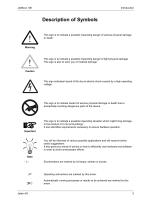
Description of Symbols This sign is to indicate a possible impending danger of serious physical damage or death. This sign is to indicate a possible impending danger of light physical damage. This sign is also to warn you of material damage. This sign indicates hazard of life due to electric shock caused by a high operating voltage. This sign is to indicate hazard of serious physical damage or death due to accidentally touching dangerous parts of the device. This sign is to indicate a possible impending situation which might bring damage to the product or to its surroundings. It also identifies...
Open the catalog to page 5
Reference to PC keyboard and HMI keys. This symbol informs you of additional references (data sheets, literature, etc.) associated with the given subject, product, etc. Further, this text provides helpful hints for your guidance through the manual.
Open the catalog to page 6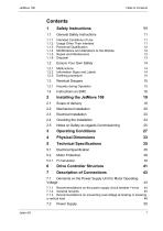
Safety Instructions General Safety Instructions Intended Conditions of Use Usage Other Than Intended Personnel Qualification Modifications and Alterations to the Module Repair and Maintenance Disposal Ensure Your Own Safety Malfunctions Information Signs and Labels Earthing procedure Residual Dangers Hazards during Operation Mechanical Installation Electrical Installation Notes on Safety as regards Commissioning Operating Conditions Physical Dimensions Technical Specifications Electrical Specification Motor Protection Drive Controller Structure 7.1 Demands on the Power Supply Unit for Motor Operating...
Open the catalog to page 7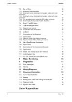
Servo Motor 7.3.1 Motor with male connector 7.3.2 Motor with screw clamping terminals and cables with male connectors 7.3.3 Motor with screw clamping terminals and cables with male connectors 7.3.4 Pre-fabricated motor cable with SC mating connector 7.3.5 Motor Cable Permanently Fixed to the Motor Stepper motor control Acceleration and deceleration Specification Resolver Cable With Mating Connector Resolver Cable Without Mating Connector Connection of the Incremental Encoder Digital and Analog Inputs and Outputs 7.11.1 JETTER System Bus Cable Specification Status Monitoring Error Messages Wiring...
Open the catalog to page 8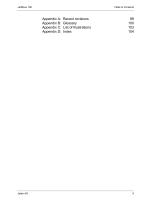
Appendix A: Appendix B: Appendix C: Appendix D: Recent revisions Glossary List of Illustrations Index
Open the catalog to page 9
1.1 General Safety Instructions Safety Instructions General Safety Instructions The digital servo amplifier JetMove 108 meets the applicable safety regulations and standards. Special emphasis was given to the safety of the users. Further, the user should adhere to the following regulations: • pertinent accident prevention regulations; • accepted safety rules; • EC guidelines and other country-specific regulations. Usage according to the intended conditions of use includes operation in accordance with these operating instructions. The digital servo amplifier JetMove 108 may only be operated in...
Open the catalog to page 11
If the digital servo amplifier JetMove 108 is to be run under operating conditions, which differ from the conditions mentioned in chapter 3 "Operating Conditions", page 27, the manufacturer must be contacted beforehand. Personnel Qualification Depending on the life cycle of the product, the persons involved must possess different qualifications. These demands have to be met, in order to grant safety in handling the JetMove 108 at each phase of the product life cycle. Product Life Cycle Minimum Qualification Transport / Storage: Trained and instructed personnel with knowledge in handling electrostatic...
Open the catalog to page 12
1.1 General Safety Instructions Repairs to the digital servo amplifier JetMove 108 must not be carried out by the operator. The servo amplifier JetMove 108 does not contain any parts to be repaired by the operator. For being repaired, the servo amplifier JetMove 108 must be sent to Jetter AG. The digital servo amplifier JetMove 108 is maintenance-free. Therefore, absolutely no inspection or maintenance works are required for the operation of this device. In case of obvious damage or erratic behaviour, the servo amplifier must not be used any more. When disposing of devices, the local environmental...
Open the catalog to page 13
Ensure Your Own Safety Isolate the digital servo amplifier JetMove 108 from the mains, if maintenance works have to be carried out. By doing so, you will prevent accidents resulting from electric voltage and moving parts. Follow the information given in chapter 1.3 "Residual Dangers", page 15. Safety and protective devices, e.g. guards, must not in any case be shunted or by-passed. Prior to commissioning reattach dismantled protective equipment, such as guards, and check them for proper functioning. Prior to commissioning, the machine manufacturer shall conduct a hazard analysis for the machine...
Open the catalog to page 14All Jetter AG catalogs and technical brochures
 JX3-BN-ETH
64 Pages
 JX3-DO16 Digital Output Module
136 Pages
 JC-310-JM - Controller module
270 Pages